Wednesday, November 30, 2022

Half-Scale Build #71


I completed the foot-well having elected to cut out an 8" diameter hole in its topside to facilitate passenger ingress. Meanwhile back at the top end there is a use for these sockets that are more normally used to fix poles in wardrobes. They also help locate our own poles during assembly in the field, whilst bolstering rigidity to some extent.

You might be wondering why I've chose to fix the rotorhead in position rather than have it rise into place with rotors turning prior boarding? Well at full scale that will be a flyer, the aircraft poised for lift-off and me racing to board under fire in my fatigues, looking very much like Robert de Niro in the Deer Hunter.

The mannekin though will race nowhere on fibreglass legs and if the vehicle won't fly with him anyway, we've more serious issues than whether the rotorhead is sliding to spec.

Top tip: orient the sockets as shown so the rivets don't catch the tubing inside.

Half-Scale Build #70


With mannekin centre-stage, mark around the feet. We'll be including a circular hole, as I don't want to take bespoke tailoring so far as shoe-size. Nonetheless it allows as economical a cut-out as possible, so as to preserve the structural integrity.

There's a twist crept in somewhere, mainly because at at this rapid prototyping stage I'm working to a millimetre. Airbus do have rulers that measure microns, but we don't.

Half-Scale Build #69


Here's the new 9mm ply pattern bolted into place, and doesn't she look pretty? You'll have noticed there's a serious omission in the form of a hole to stand in, which we'll get to next.

Half-Scale Build #68


Get my best ideas at three in the morning generally and figure I can lower the profile of the foot-well by using an identical pattern to that of the mid-riff retainer aka flight-deck. To do that I've taken an inch off the uprights at each corner (now 2.75" each) so as to include a threaded M6 insert. If you've been following my instructions and can't believe this is the second modification to the wheel-well, then bear in mind that it's a character-building exercise you'll get no place else.

Tuesday, November 29, 2022

Static Load Test


One for archives? The rotorhead took a bit of walloping with a rubber mallet to knock it into place, but I've built dozens of frames and they rarely needed wrapping in cotton wool. I did carry out a risk assessment for this exercise that concluded it might end in injury or death, but as it wasn't my 'cock on the block' I gave it the go-ahead.

That's 40kg or nearly 90lb up top, supported by sixteenth-inch tubes 19mm diameter. Engineering students among you will know that the columns would eventually fail by splaying apart, buckling and crushing Monty in the process. What prevents this is the flight-deck, set at 500mm above the foot-well and cutting the effective length of the columns by 50% to increase their strength disproportionately.

They test airliners to destruction during development, bending wings up with hydraulic rams until a horrendous BANG as they fail at the root. I'm not going to do that here, but I have decided to up the width of the columns anyhow to a full inch. Yes it's over-engineered, but I prefer to come at it from that direction than the other.

Half-Scale Build #67


I've made the decision to test the prototype in the first instance with the rotor-head locked in the uppermost FLIGHT position, and as a result I've been able to reduce the circular tubes to just 1050mm and need only drill the centre-section of the top end at 6mm instead of 20mm or thereabouts. Here I am allowing for the internal width of the alloy sections and positioning a bracket to match the bottom and middle sections of the air vehicle.

Quiz


Study the above carefully. It's a...

    (a)    Minecraft Polar bear

    (b)    Personal air vehicle safety-restraint

(4 marks)

Monday, November 28, 2022

Half-Scale Build #66


Monty the mannekin, set to fly! Wish I'd used one-inch poles, but prototyping is about practicality and not perfection... the aim being ever to inspire.

Half-Scale Build #65


With just a little sanding I was able to park the flight-deck around the topside of the mannekin's lower half. I've warned the guy however that he'll be needing to stay off the beer during the FIFA 2022 World Cup that we're both currently enjoying.
 

Half-Scale Build #64


Though not appearing in the patent drawings, most people not in a SWAT team would likely baulk at the idea of simply hanging around in a four-bar cage at a great height, and so some form of restraint looks essential ~ and it might as well be combined with a form of flight-deck for any time you need to do the flying. I've actually got templates somewhere in the workshop that literally describe my own beer-gut, and it did prove to be a practical proposition to practically 'wear' a personal airframe. Again these are likely to be bespoke items for maximum comfort... "Suits you, Sir!".

What I've done here is rather than fashion a generic void in the deck, I've been able to sketch around the mannekin's midriff because it comes in two halves. The elbows do coincide however with the waist a little further upwards, though I figured if the deck fits around the hips like this, then it's likely to so beyond. Incidentally when we look at centre of gravity issues, a Google search suggests that your own centre of gravity does coincide with a point that coincides more or less with your belt-buckle. Figured it'd be higher than that, especially with a brain my size...

Half-Scale Build #63


I check that it fits the uprights, which it does. Note how it adds to the integrity of the overall structure, all be it not totally immune to a degree of twist. This is nothing to be frightened of, however: I used to marvel while waiting to taxi how MD-80 airliners would bow like a sausage-dog over every bump. Likewise the fuselage of the 757 was renowned for twisting remarkably along the length of its cabin.

Half-Scale Build #62


Here's the flight-deck after being jig-sawed and drilled out with a 20mm spade drill. It looks a bit like a Minecraft teddy-bear, doesn't it?

Half-Scale Build #61


Next I draft lobes of around 80mm square either side, to support the sidesticks.

Half-Scale Build #60


Looking at the mannekin when stood inside the tubular columns, I mark out the likely position for left and right sidesticks using the excess around the border.

Half-Scale Build #59


Turning to the flight-deck, here's an old piece of 9mm plywood that will do the job. I start by marking out the outline of the foot-well and drone centre-section in the form of a 305mm square. There's an excess at top and sides which we can use in due time.

Half-Scale Build #58


A bird's-eye view and you can see why I wanted an articulated mannekin. I must have got one of the last few of this type in the UK prior to the arrival of a container at the end of next February... and it was Goethe I believe who said that when you set out on some or other venture the Universe conspires to make it happen?

I've a piece of plywood too left over from the last build and which I can use for the 'flight-deck'. One thing I discovered from building for the competition in California was that if you fix a 'stay' fixed half way up the columns, then their length is effectively halved and they can support a great deal more weight. What the 'flight-deck' will do,  pulled up like Wallace and Gromits' trousers, is to reinforce the columns as well as providing an active means of control.

In terms of pilotage, a reason I want the avionics fitted on the underside of the drone is that then you've an overhead panel like in jet airliners, with controls accessible to the aircraft operator for engine-out procedures and so forth. Another advantage of the layout is that with the motors shut down and propellers windmilling, the vehicle will descend like a parachute; unlike most eVTOLs. I learned to fly with both helmet and parachute, and worst case here you'll release the platform and bale under gravity.

Someone looking at these drones once said that I thought of everything... and I do.

Monday Round-Up (MRU)


I'm going to make these a feature of the blog if for no other reason than to preserve my sanity. Firstly you might be wondering how the foot-well element of the personal air vehicle came to look so different after so much earlier effort. The simple answer is met by Dyson's dictum that you learn nothing until you start building. Less than ever that is not so true at all nowadays: if you've a design department and finite-element analysis software then you can 'build' prototypes and stress them on-screen during a cappuccino. With the metaverse around the corner too, there'll be three-dimensional look-and-feel in a virtual reality, with products going direct to robotic 3-D printers and human beings barely getting a look-in.

To many people this sounds like the ideal world, although to a great extent what we've found as a Western civilisation in particular is that every advance that means we don't have to spray-paint parts in sub-zero temperatures also means that life has that little less meaning. My son already prefers life inside a computer game, and he's not wrong: it's the biggest business on the planet and only set to get bigger. So I recognise I'm a dinosaur but as Dylan Thomas (and I've seen his beach-hut) said at his dying father's bedside, "Fight, fight against the dying of the light."

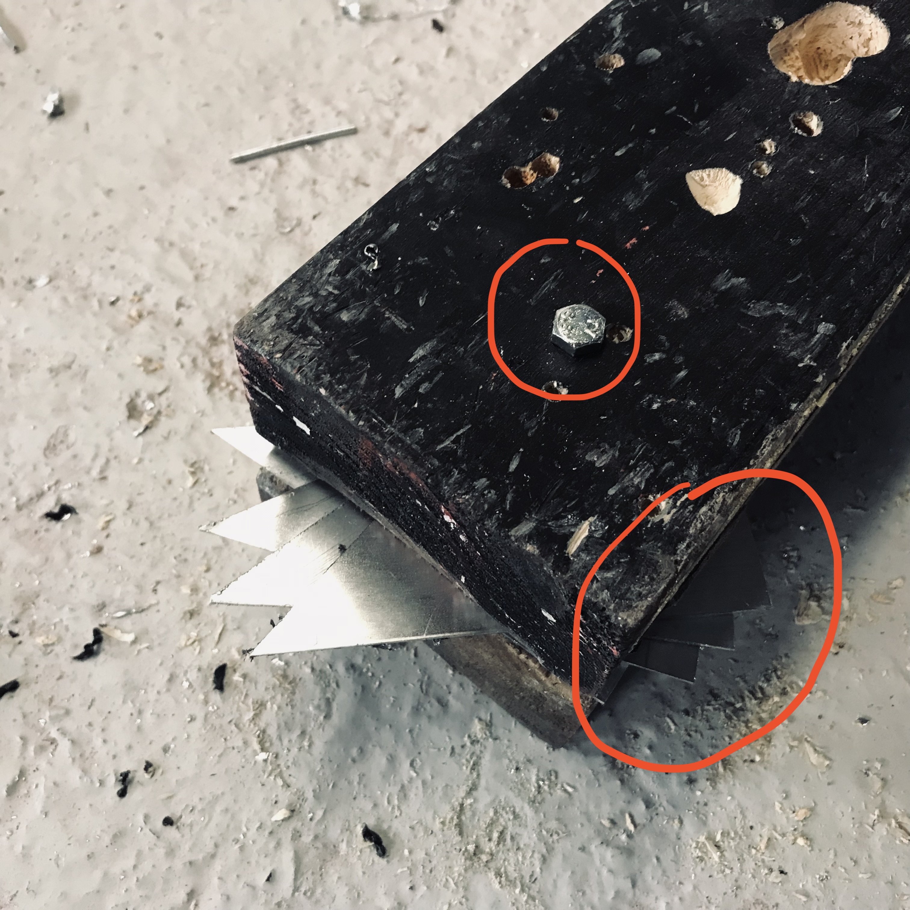
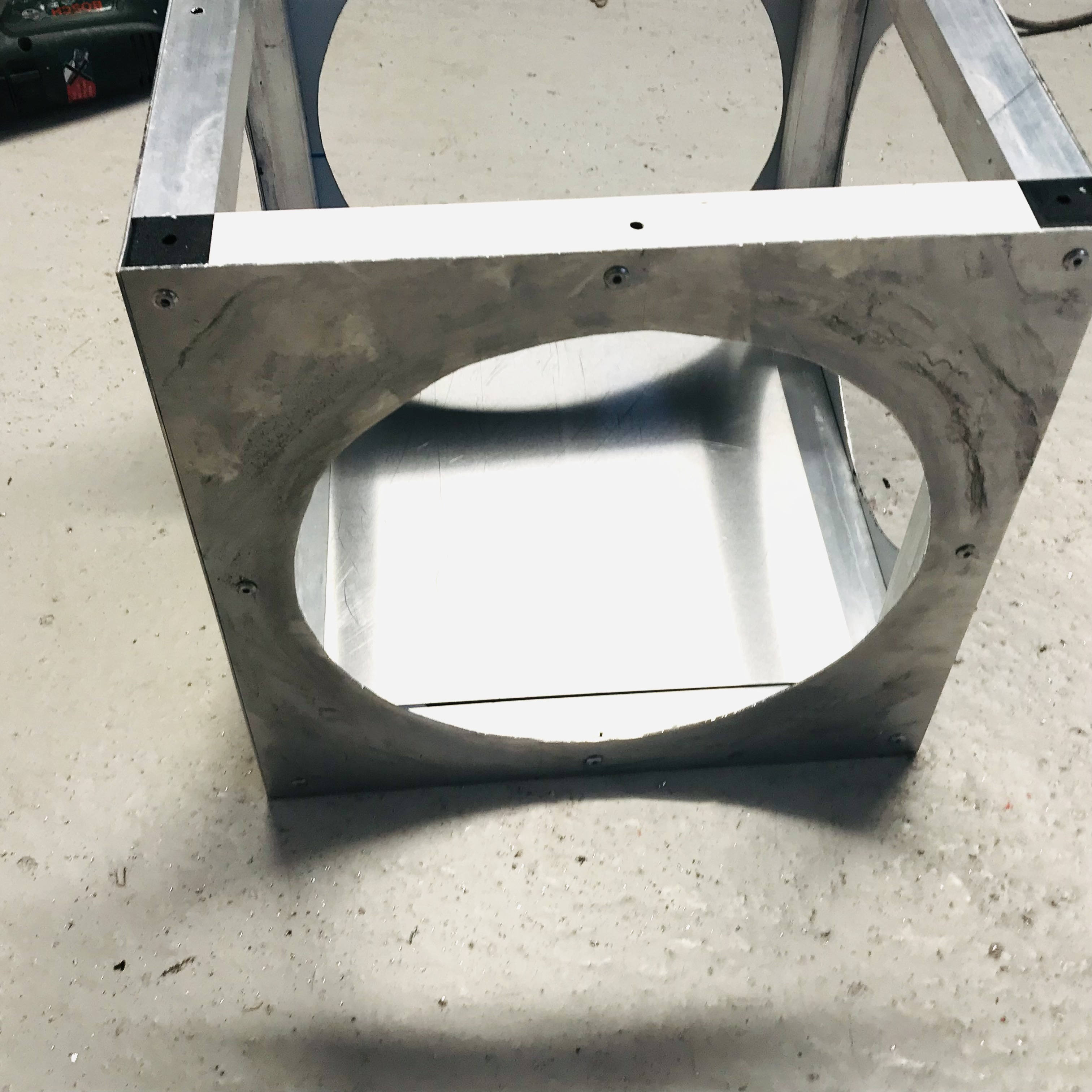
To return to more prosaic matters however, firstly the weight of this part had to be cut drastically, even at this stage. Secondly I wanted it to accord to what had appeared in the patent diagram as closely as was practical. Thirdly I did not like the holes in each of the side-panels, as the product aesthetic is so far as is possible, square. Fourthly this one is a whole lot easier to step into in ergonomic terms, especially with rotors spinning on the overhead as they will be. And fifthly, because it's my party.

I'm relaxed however at it knowing it would be a fraction of the weight and a whole lot stiffer in carbon-fibre, but that's an ace up the sleeve. The mannekin itself is a whole lot lighter than a real three- or four-year old, and so a bottom end being heavier than needs up restores the balance somewhat for testing.

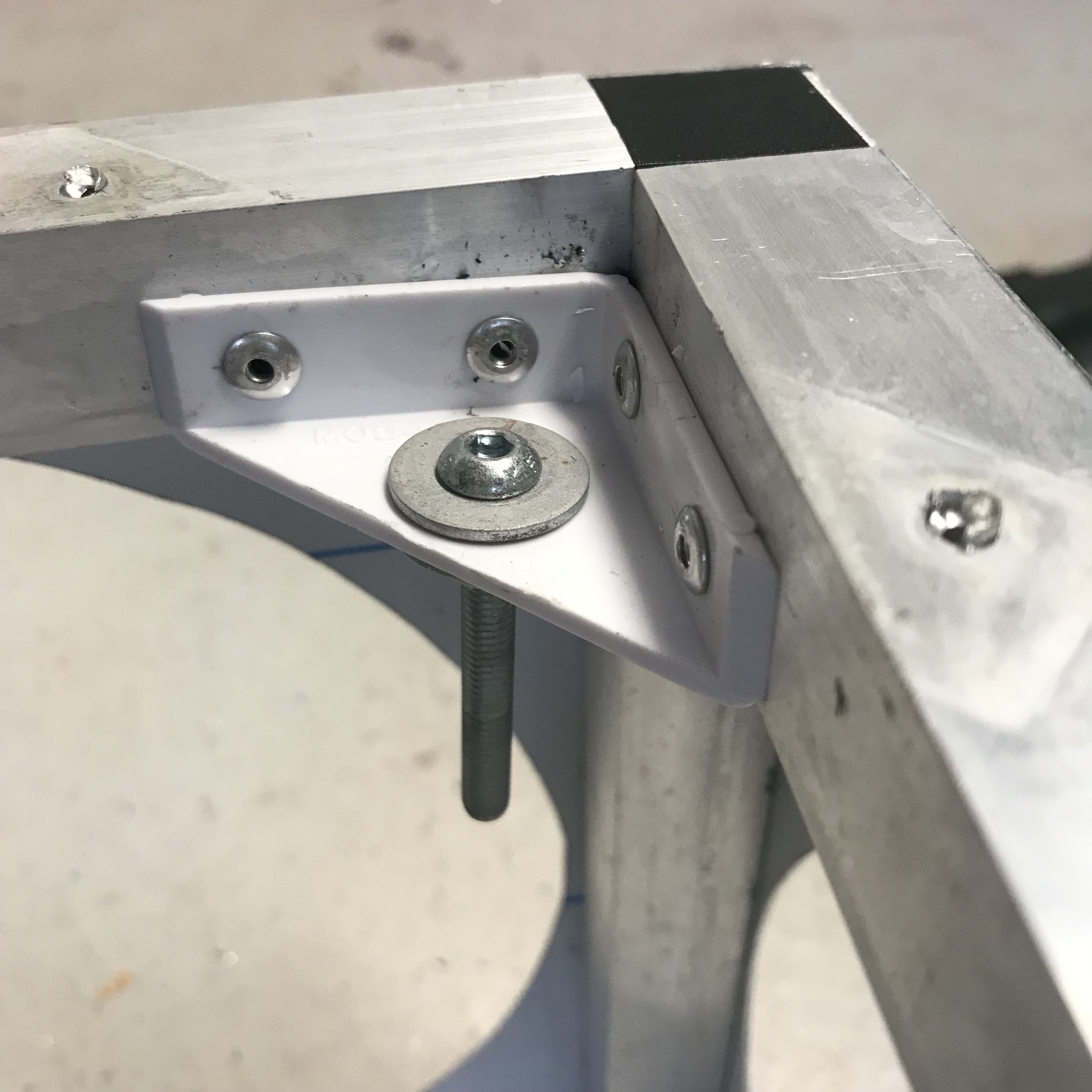
The important thing is that ~ and probably a first in eVTOL or PAV design ~ the product is designed in separate modules viz. foot-well, connectors, harness and drone. Each of these is effectively independent and could be contracted out to specialist suppliers in the say that, for example, you'd deal with Shimano rather than build derailleur gears.

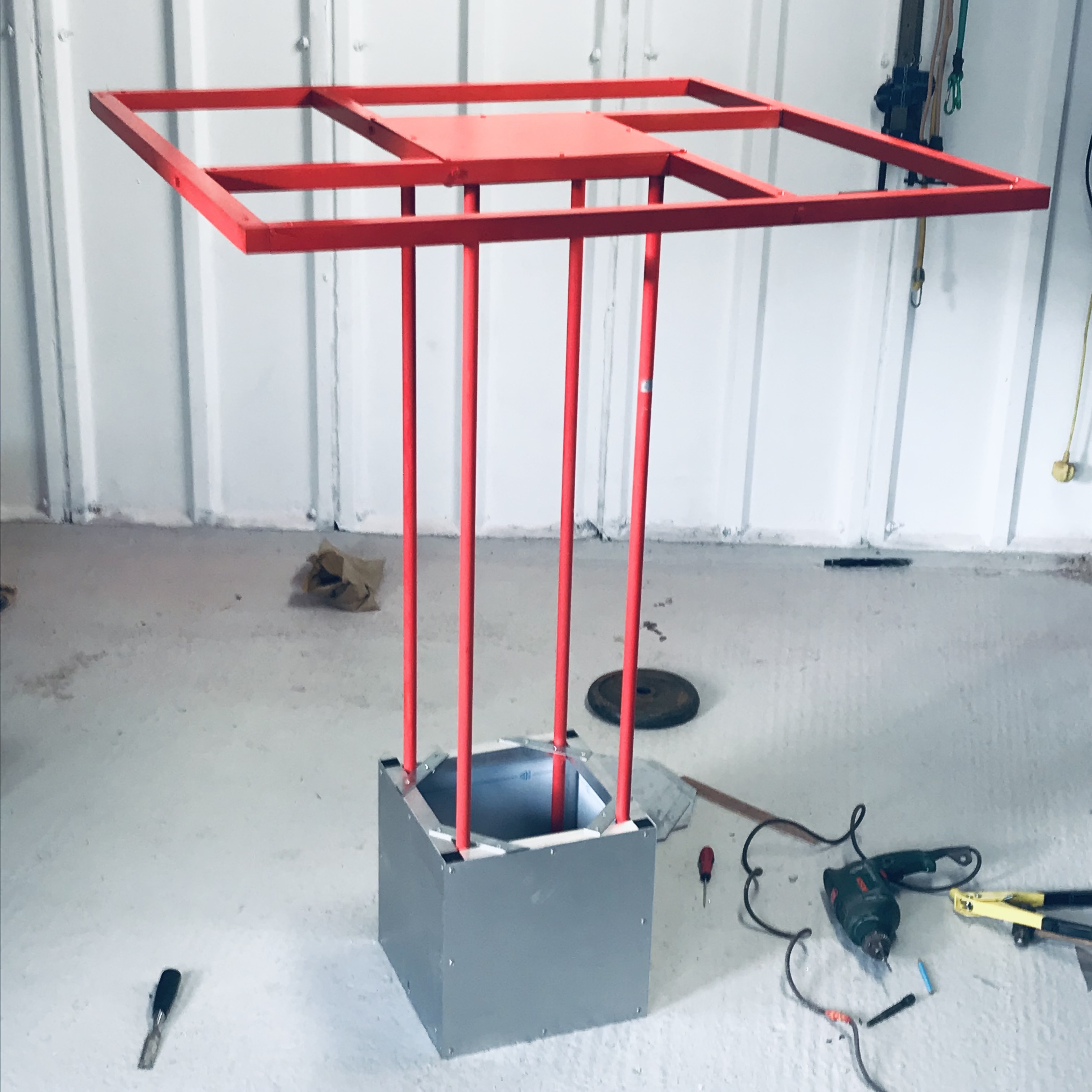
From my own point of view ~ and this is probably true of aircraft design generally ~ the prototype has to look increasingly credible at each step of the way. I've designed three previous layouts on a broadly annual basis, and each of the foregoing were impractical in ways that you could only have known by hauling them around on a trailer (or indeed shipping them as checked-in baggage between London and San Fransisco).

Each of these previous lessons has been incorporated in the current proof-of-concept, which is in many ways the one I wanted to build at the outset... albeit modified along the way by a process of live-and-learn. The best you can hope to do is to inspire, and I am gratified that the response to the '22 build is proving universally positive.

This week and following success in using giant drill-bits in your old man's hand-drill, I intend to adapt the rotor-head in the same way as a sub-set of flight-testing. At this scale we could lift the power-assembly and bolt it on top of the four columns, but at full scale you'll be lifting a great deal of weight in an effort to dock it with an overhead assembly. That is a lot easier nearer ground level, beside any question of stability even arises.

We'll also fabricate a harness-come-flight-deck for those 'white scarves' in particular who prefer to stay in control of the flight instead of trusting the AI to beam them up. 

Sunday, November 27, 2022

Half-Scale Build #57


We don't want to make any mistakes in shortening the rods if we're able to, as we are in this case. I like the idea that ~ like choosing snow-skis from the rack ~ we'll be able to select a set of rods to suit the flying machine to our own height.

What I'm doing here is firstly to mark the height of the mannekin on a sample rod that is screwed home fully. We must also allow for the thickness of the rotor-head that the rods will pass through, which is 1" or 25.4mm.

The last time that we flew a drone of this size and shape we did so with motors and flight-controller mounted on the underside. Though we'll be mounting motors on the top-side this time, I'd still like the option to mount the controller in the same place. It is 30mm (1.25") deep and we need to allow for this above the mannekin's head.

I will reduce each rod to allow for all this to 1100mm (43.25"), not including inserts.

Half-Scale Build #56


Now with our 'Head of Ergonomics' hat on we can replace the mannekin and measure it up against the con-rods. I'm pleased with the mods to the foot-well as its weight is reduced to just 1.50kg or 3.50lb.

Half-Scale Build #55


Here's one of the brackets being rigged with the rising column prior to riveting to the framework.

Half-Scale Build #54


Having drilled two blocks with a 6mm holes too, line them up with the sheet-metal brackets by using a bolt of the same size. Then remove the bolt carefully in readiness for drilling with a three-quarter inch bit. You can use G-clamps to secure prior, else simply stand on it as I did. It's the only way (without a laser-cutter or CNC machine in your garage) that you'll be able to use a larger drill-bit without it launching the hand-drill across the floor at speed.

Half-Scale Build #53


Drill a 6mm hole in the template to coincide with the dot made by the marker-pen. 

Half-Scale Build #52


Here's the template that shows where each of the connecting-rods will be bolted into the brackets around the base. We'll be using this along with three more as guides that maintain the verticality of each rod.

Half-Scale Build #51


Weight at the bottom end is to be avoided, pitched as it is so far from the C of G (or centre of gravity). Nor indeed did I like those circular cut-outs that are so wasteful of material. Finally we have to consider passenger ingress, for even if we view this as say a two-thirds scale model, that still means the original box was around eighteen inches (forty-five centimetres) high, which is a big ask for people to step into at all easily.

Accordingly I've dropped what we shall call the 'foot-well' to half of its original height and left the side-panels off altogether. Yes, I would use them were they carbon-fibre sheet (and without the cut-outs) but no, probably not worth the added weight here.

Saturday, November 26, 2022

Life of Py... thagoras


Am probably not the only one to have sat in class wondering what use geometry had for anyone, and in fact it might have helped if we'd been told what the word meant at the outset: a means of measuring where we live. In truth it came up again in various studies toward a commercial pilot licence, though I've probably re-forgotten that now.

Here though a check on what size propeller we can fit, by taking the lengths between the corner and each axis and squaring them to find (by adding the result together) the square of the longer side. Take the square root of the sum ~ as you can do on a phone ~ and you've 29.25". This in turn gives a gap of over an inch between propeller tips.

By reversing the calculation you can of course calculate how large a given frame has to be to suit a given propeller... something I maybe should of thought of before asking the aluminium supplier to cut to stock metre lengths? The answer being a 40" frame so long as you can accept a half-inch of tip-clearance.

Which would make it just that bit easier to get into the car... life though, isn't it? From hereon in then ~ sticking to Imperial measures ~ I shall ever refer to it as a 40" frame.

Half-Scale Build #50


Here's a view of the cube from the underside. In order to make up to some extent for not having overlapped it and riveted it to the frame too I have at least sealed the gap with silicone. I prefer this to glue for prototyping as it's surprisingly adhesive in itself, and unlike glue it allows builds to be dismantled for modification... as we saw already.

We'll finish off the topside in plywood, because I've run out of sheet alloy and won't bother buying more in view of the spectacular waste those cut-outs have created. At the same time it's a whole lot easier drilling ply at larger scale than it his sheet metal. 

That said I found a workaround to stop large drill-bits chewing up the metal, by using timber clamped either side. A prime consideration however is that I selected three-quarter inch and 19.5mm metal bits, neither of which allow enough room for the con-rods to slide in, plus wood-bits at that scale are around five times cheaper.

Half-Scale Build #49


Here you can see how those bolts pass through the floor to secure it in place whilst at the same time providing an attach-point for the con-rods and hence the drone too.
 

Half-Scale Build #48


Had I overlapped that floor inside then I could have secured it in place with G-clamps at this stage, but I didn't and so let's grit our teeth and live with it shall we? Instead I have parked it on a length of timber so that I can mark out where it has to be drilled in order to secure.

Half-Scale Build #47


Annoyed with myself here because I've cut a 10" square from the remaining aluminium sheet, whereas I should have cut a 12" insert and lopped diagonals off each corner to allow for the uprights. Nonetheless the art of prototyping is much like the progress of a battle, driving ever forward regardless of individual defeats upon the field.

This section forms the platform for the passenger and it's affixed to the interior rather than to the outside because for this working model I've chosen to support connecting rods with bolts in the floor. In case these fixtures come loose we will need access to them from both sides, which would not be possible if we sealed the underside.

Half-Scale Build #46


And here's Monty the Mannekin himself (although he looks to be non-binary). Seems a little nervous and so I tell him that "It's one small step for a mannekin, one giant leap for mannekind." I was happy with the con-rods appearing largely upright, with just one of the corner brackets requiring the hair-dryer treatment to correct. Looks too like we shall be able to take a bit off the top end of those rods too.

Half-Scale Build #45


Fit the nuts and bolts temporarily in place to check the rigging and the ergonomics of including our fearless 'crash-test dummy'.

Half-Scale Build #44


Here's the cube that will make up the lower end of the aircraft, with holes cut out of all four sides ~ unnecessary with carbon-fibre sheet ~ and corner brackets riveted in place.

Half-Scale Build #43


Here's the finished article. I've used plastic brackets instead of steel so as to reduce the weight again, although a benefit of the latter is that you can knock it into place with a hammer. I'm probably the only guy out there building flying machines using a lump-hammer. An alternative that we might need to set these products straight is a heat gun, which we shall look at in due time should the need arise.

Notice that the perforations in the sides of the box make for altogether easier access, but nonetheless I do intend to retain solid sides going forward in order to recreate the telephone-box zeitgeist. Clearly carbon-fibre sheet is the outstanding material for this part of our air vehicle, because having to dispose of practically half of each aluminium sheet pierces my inbred sense of thrift.

Note too that the brackets are arranged with each face lying within the frame, so that the bolts that they will support do not lie outside the box and scrape the floor. The bottom-end of each con-rod will include a nut to screw into the bolt in each bracket. 

The debate between studs and bolts has most often been seen in fitting car wheels. At the time I bought my first car whilst still at school, cars used nuts to attach wheels to hubs whereas now they invariably use studs and the hubs themselves are threaded. When did that sneak up on us?

Half-Scale Build #42


To create the 'stays' that will capture the lower end of what I shall call the connecting rods joining rotorhead and passenger platform, I have used kitchen-cabinet brackets. When you call at the hardware store for these, be sure to ask them for aviation-grade brackets as well as tartan spray-paint and a long weight... and say I sent you.

What I've done here is select a corner-shaped off-cut and used it as a template along with a couple of off-cut tubular sections. Then using a market we will be able to carry the location of the bottom-end of each connecting rod upwards to the same point on the upper side of the box in which the pilot/passenger will be stood. If that makes any sense at all to you, take a lollipop. Everyone else, be assured it will all come out in the wash.

Half-Scale Build #41


With nerves a little frayed from the mission-creep on the weight side of things, I take the decision ti include circular cut-outs in each side of the box supporting the pilot, and this reduces its weight by 25% at a stroke. It is also the oldest trick in the book for people who build aircraft ~ open them and they contain more shear-webs than a spider's backside.

Easiest way to do this I have found is to drill a central hole and drop a bolt through the end of a ruler (which often include a hole for hanging them up), and then drill a second at the required distance. Insert marker pen in the latter and rotate. The pen, not you.

Friday, November 25, 2022

Half-Scale Outline Drawing


Guide for where we're at and one for posterity. Only thing I've omitted is the fact the framework is built in 1" section (at a sixteenth). Would like in retrospect to have used columns of 1" section as well to support the drone in the overhead, but we're too far gone for that now and hence those four perforations are three-quarter inch apiece.

This outline will swing the largest propellers used with U11 motors, yielding fourteen kilos each at max thrust and an extra half if over-boosted with seven-cell batteries.

We'll be cookin' on gas...

Half-Scale Build #40


How the 'stretch' should look on completion ~ weighs in at just over eight pounds and just under forty-two inches. It's a tight fit in the back of the Jimny by should slip into the hatch of practically every other vehicle on the road. All in all a good week's work and as none of us are 'Muskovites' it has to be time for a beer during the England v. USA '22 World Cup soccer match.

We'll win of course... building the better soccer teams as well as the better drones.

Half-Scale Build #39


Re-rig as appropriate. Best thing about drones is that this need not be overly precise as the flight control computer picks up the slack and keeps things straight and level.

Half-Scale Build #38


Overlay the completed mod on the frame work, leaving connections loose for now so as to facilitate drilling 6mm holes in each side in support of the centre-section. Mark off where those holes need to be as shown.

Half-Scale Build #37


I recommend removing and replacing a leg at a time. Here I have re-purposed parts of the perimeter frame from the previous build, even lining up previously-drilled holes to suit.

Half-Scale Build #36


I'm including these posts as a guide to how best to adjust the airframe size to suit a range of different motors, as I have decided to prior to electrifying. I've selected stock metre lengths because these suit carbon-fibre builds beside alloy. After unbolting the centre-section from the previous build, I've rigged it on the workshop floor in the best tradition of shipbuilders ~ it's a belt-and-braces check that I always rely on to back up calculations and measurements. I needed to up these cantilevers to around 630mm.

This is the advantage of commercial-off-the-shelf building in alloy... no messy welding, nor composites to bin.

Three-feet good?


We saw yesterday in a cost-benefit analysis the quad wins hands down for our current purposes and I overlooked the cost of speed-controllers. To power an octo with 22" props now costs $3300 at China prices, and for a quad at 26" or 27" it is $2500.
 
And whereas I planned to address each of the smaller U7s on the octo with its own battery, I've a larger pair of six-cell packs that I can gang together and feed all four motors of a quad from a single source. (They'd have to be wired in series in that case view of the fact the larger U11 motors for a quad run at 45v instead of 22v for the U7s).

An option at this stage is to use the existing three-foot frame with the U11s and larger propellers, subject to those front and back mounted topside and those left and right underside... in which event we can squeeze 26" props on the existing frame so as to provide the required 20kg of thrust. Alternatively we could run with top-side U11s if we enlarge the frame to one metre instead, though to do so we have to check the logistics of carrying it around.

Looking at the photo it clearly passes the 'Jimny' test at either size, and what it shows too is the practicality of adding a perimeter to the four-prong design patented back in 2014. In itself this neither sat flat in a car nor upright in a van, and its prongs poked people in the eye. Nor did it track normal to orientation, so the flight controller had to be mounted at an angle.

In fact if I've achieved anything to advance the cause, then it's that square.

"And the Oscar for Best Airframe goes to...".

Thursday, November 24, 2022

Cost Benefit Analysis


The mannekin of choice is container-bound like so much else in the modern world and not expected before the end of February. Common traits entrepreneurs share are impatience ~ Elon Musk at the end of the spectrum ~ and a reluctance to compromise which was best expressed by Steve Jobs. Human progress stemming, as Bernard Shaw observed, from those least reasonable.

For our unenlightened selves however this requires a decision, and there is a firm out there who'll rent the same mannekin for measuring up purposes and PR shots, so it need not hold us back. As it is I've viewed so many child mannequins online that I fear a knock from the vice-squad any day.

Meanwhile it's clear that the U7 motor will provide not nearly enough power as a quad, especially as said mannekin comes in wood and fibreglass. It will be struggling to lift the payload at max chat and therefore we need to look at an upgrade. In the long history of aircraft design to-and-fro between airframe and power-plant is a perennial issue, and as often as not it's the airframes that depend on the engine manufacturers moreso than the other way round.

We can up the motor-count like the designers of the Avro 146 had to do when two jets were not sufficient, else fit larger power-plants in the way aerospace evolves toward: so we can maintain our 36" airframe and add four more motors and 22" propellers as on the right, or up the frame to a metre and fit larger U11 motors and 27'' propellers.

Surprisingly the octocopter produces much the same thrust at 60% throttle, not least because it sweeps 50% more disc area (although you could probably reduce its performance by upto 10% due overlap)... 18kg. The quad delivers 21kg at that setting, or 20kg with 20" propellers.

The differences between the two arrangements however lies in:

(a)    price
(b)    practicality
(c)    plausibility

The quad costs around $2500 to motorise whilst the octo costs around $3300. It also has motors and rotors on one side and is more easily transported without damage. For PR purposes too it has cleaner lines and is the more relatable for experts and public alike, who can see that four more motors might coincide for engine-out capability.

Construction to date will therefore be used as a look-and-feel representation of the working model, which will incorporate all of the lessons learned to date.

Wednesday, November 23, 2022

Half-Scale Build #35


Thirty-five steps in it's maybe worth stepping back to see if it's worth going forward and it does look as though it will be a flyer. In view of the setback relating to drilling  over-size holes in the airframe I shall fix the rotorhead in place with 6mm bolts. The important thing is that in terms or portability the machine will separate into box, rods and drone... in the past a problem with the layout has been the necessity for a trailer.

I've identified a suitable mannekin by way of a test-pilot, however, so I shall pause the proceedings because the vehicle has to be tailored to suit. This is one advantage of a modular approach, in so far as the height of the assembly can be adjusted to suit that of the operator. Which itself would be a first in 4th short history of eVTOL design.

Tuesday, November 22, 2022

Half-Scale Build #34


Interim weight check as we need to be under 55 pounds (25kg) all up. The box weighs 3.70kg and the rotorhead 3.50kg, with the risers an extra 0.90kg for a total of 8.10kg or 18 pounds at this stage of the game. They're by no means big figures for mega-sized drones or indeed 'personal air vehicle' scale models, in view of the fact the eventual full-scale target weight need come in at 250 pounds.

Nonetheless I'm disappointed. I'm mentioning no modules, but you know who you are.

Well okay, the box added more than I would have expected, but like every other part it could be significantly reduced by the use of carbon fibre or yet a narrower gauge tube. A more immediate issue is that that weight is pitched decidedly somewhat beyond the centre of gravity, which will have an indeterminate effect on manoeuvrability.

More a stumbling block at present will be how to attack the rotorhead with the giant drill-bit given today's little lesson. We could of course simply bolt the drone on top to see if it all flies, but that somewhat defeats the proof-of-concept.

And I've never let real-world practicality stand in the way of progress in the past...

Sleep on it, I say. Not Tesla where working for here, is it?

Half-Scale Build #33


A quadrant here including a precisely drilled three-quarter inch hole proved not to be possible with a fixed speed hand-drill, so we've resorted to Plan B in the shape of a steel mending strap. As carbon fibre strip comes cheap, this may prove to be practical longer term. Ugly and adding an angle-grinder to the must-haves, though needs must.

Half-Scale Build #32


Check the risers are rigged true, and if so then secure the base of the box.

Half-Scale Build #31


Secure from above... will need to be nylocs so as not to work loose.

Half-Scale Build #30


Drill from the topside and insert domed 6 x 50mm bolt from below.

Half-Scale Build #29


Using a washer of matching size, trace out the risers, inset from each corner.