Wednesday, June 15, 2022

60" Build Step #40

And take a picture. Whether it would be anything either you or I need let alone anyone else, given the parlous state of the world, is moot, for few of us after all are anything like Richard Branson and his need to flit between one of his Caribbean islands and the next.

But then it is what it is, and I'm proud to have brought it this far.

Tuesday, June 14, 2022

60" Build Step #39


Mounted this on the flat-bed at four points, not unlike the twist-lock system on your freight container, and lifted on inverted from off to one side. Could do with rails so as to slide it into place and save my back, particularly once there's the weight of motors to consider. Also an argument for the 36" props and a frame nearer 52" than 60", but this will have to do for starters.

Monday, June 13, 2022

60" Build Step #38


Here's the power installation, and for the final cut I've made a facsimile of a Fullymax 12S pack of 5600 mAh that is normally used for RC helis, but which we may just get away with here. It is the type that includes a pair of six-cell packs sealed end to end, so that the cables would appear from the right in the picture.

From thence they power the ESC, which in this case is a facsimile of the Flame 180A that we've used before in test-flying. From the right-most end of the ESC, therefore, the batteries connect to the underslung motor.

Am pleased with the (wooden) mock-up battery-packs, as they represent a first foray into shrink-wrapping.

Sunday, June 12, 2022

60" Build Step #37


I re-fit the looky-likey motors and take the opportunity to correct the fact the props all appeared to have been running in the same direction.

The control logic we're using was likely the very first applied to quadcopters, it being most straightforward. It is no longer in common use among model drones, it being aerodynamically sub-optimal as speeds increase... racing drones therefore invariably feature 'X' frames instead of '+' types like that here. Nonetheless design of people-carrying drones is invariably a compromise, so I've pursued operational practicality and cost-efficiency over speed.

What you see in the picture is still not entirely correct as the clock-anti-clock-anti sequence seen in the inset is generally viewed from above, and this is the underside of our drone. Yet something else you learn quickly in this game is that the perfect is the enemy of the good.

We've just the look-and-feel of the electronic speed controllers (ESCs) to contrive and then this baby's good to go, for PR purposes if nothing else.

Saturday, June 11, 2022

60" Build Step #36


Many emails ask, 'Master, how do we wire our drones? Teach us, that we might know.'

And indeed we are at a juncture as we need to decide to use a common battery bus or a distributed power arrangement. And do we go for flat packs, or bricks like these?

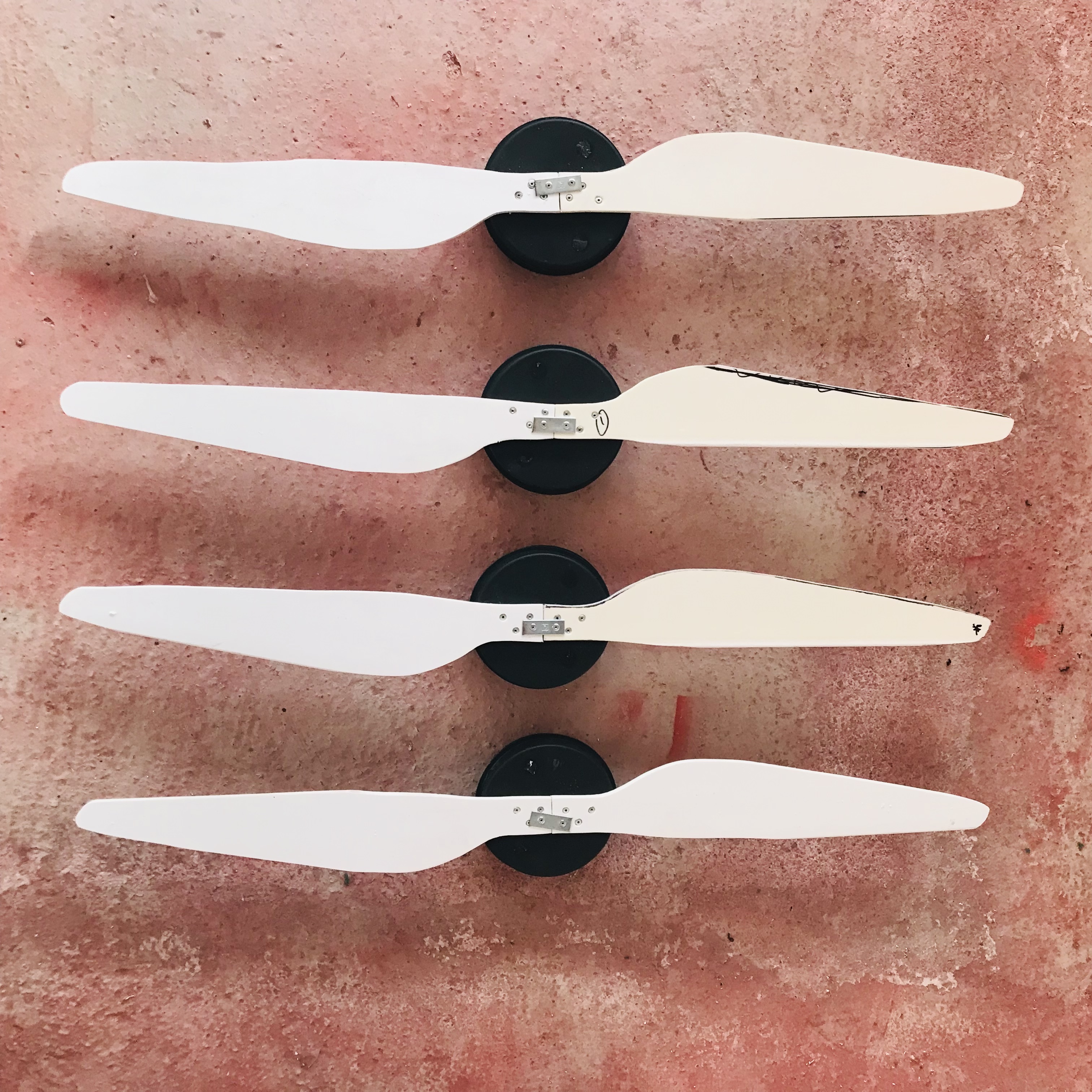
This is the pilot-eye view of an auspicious arrangement going forward. You will have seen how we modified the airframe to make all four sides match, so what goes for the front-end here (now marked by an arrow as a reminder) goes for remaining motors.

These are six-cell packs that we have most often used in the past for test-flights, and generally just two of them wired in series was enough for trial runs of prototypes with eight U13 motors. With a switch to larger U15s at nearly double the wattage, however, we need to up our game.

A distributed power arrangement where batteries address motors directly and may be co-located can be seen in Lifts 'Hexa' prototype, though one is also used in Dragon's 'Airboard' in Florida, flown by the fragrant Mariah. Notice in the latter case that four pairs of packs like these power eight U15 motors, and for a surprisingly long time.

We could therefore up the voltage and use seven-cell packs of a smaller capacity than the 22,000 mAh types seen here. This would lower the weight of the machine, so that for test purposes a 'virtuous circle' operates wherein lighter batteries have less to do.

Nonetheless I've gone with the stock option for the moment and packs in regular use with the heaviest drones. A benefit of how they fit here is that the perforated grille that allows the propeller to breathe also forms a pegboard for pop-rivets. This means that to switch from six-cell packs to seven-cell the rivets need only be drilled out and the angle-alloy stepped back to accommodate the wider type.

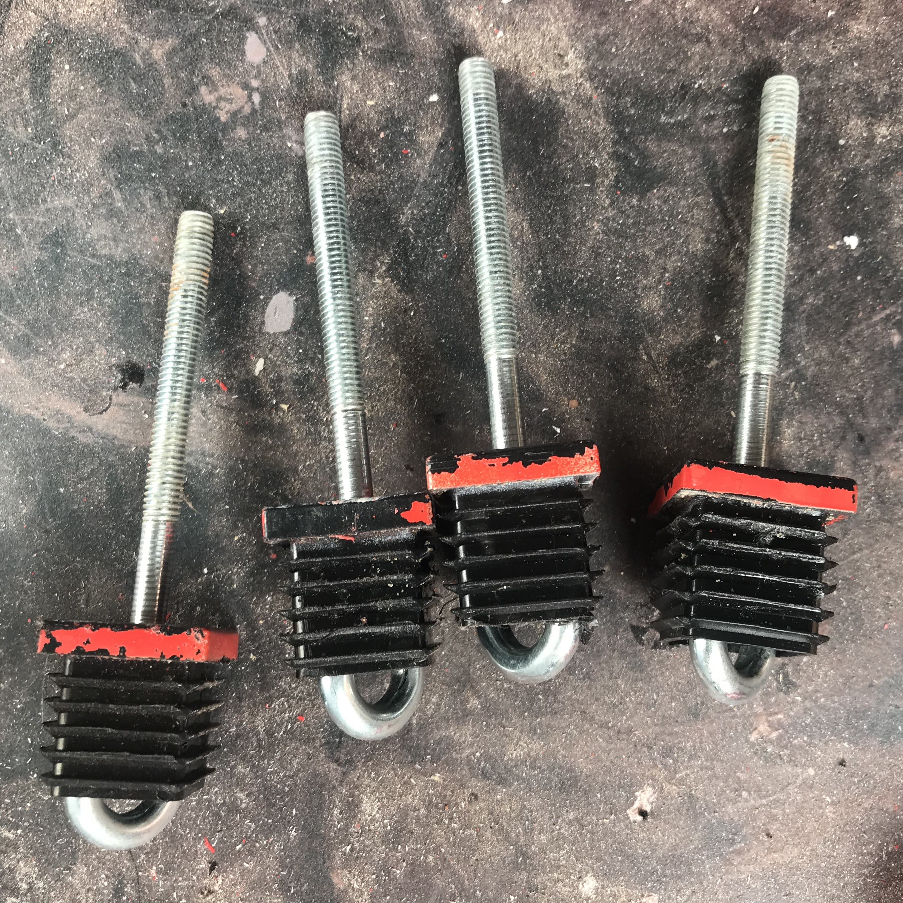
To ensure that holes in the angle-alloy coincide with those in the grille, clamp it in place and go in from the underside ~ which practically means upending it against the garage wall.

I did consider batteries under-seat along with power distribution board and associated wiring, but there were three reasons why not:

(1)    If they caught fire I'd have a very hot bottom.

(2)   I'd like to reserve the under-seat space for avionics.

(3)   They're easily connected from within or without the vehicle.

Friday, June 10, 2022

60" Build Step #35


Departing from recent development I've come to a compromise with regard to the use of safety grilles, and taken the arrangement at the front of the vehicle (lowest edge seen here) and applied it to all four sides. This has several advantages: half the weight of the original all-encompassing mesh it still extends substantial protection all round, besides being both purposeful and practical in terms of design criteria.

You'll recall from schooldays that if you were ever to fall off a chair with no restraint, it would be forwards, sideways or ~ everyone's favourite ~ backwards. What I've gone for here therefore is an outline that won't burden test-flying, yet which could still be carried forward to production types.

To make it I've simply applied sixteenth by one inch (25mm) angle alloy so as to form a tray into which perforated aluminium sheet is pop-riveted in place. To do this I have had to remove three of the motors because all four will now be braced by this section of alloy along the inside edge, with bespoke bracket now required only along the outer.

This in itself reduces the part count whilst providing a commonality of construction. So far as the latter is concerned, most of us assembling a set of IKEA drawers will be aware that the process is a whole lot simpler once you've made the first of these. 

As regards parts count, among the most successful British armaments was the STEN gun, not least because ~ according to a museum I visited in Arnhem ~ part count was reduced by no less than two thirds by a pair of Czech engineers.

Thursday, June 9, 2022

60" Build Step #34


Here's an overview of the power set-up for you. Note the practicality of using stubs at each corner when it comes to storage, handling and maintenance and beside this I've taken the opportunity to install bridge handles for general manoeuvring, which attach to the flight-deck with four M8 bolts.

Working with the airframe is a lot simpler with safety grilles removed, as you can step inside its perimeter to pick it up. Going forward these will be units dropped into place when preparations are complete, though for the purposes of test-flying the semi-grille shown will do. Though perforated their material is actually quite weighty, but there are perforated plastic sheets available which may improve on the aluminium.

Wednesday, June 8, 2022

60" Build Step #33


We'll still mount those mock-up motors by identical means, and to do so I've removed the seating plinth and inverted the airframe so as to apply a pair of six-inch brackets. 

These are oriented face-down, so that they essentially reinforce the perimeter tubing in resisting the upthrust. In many ways this is a more satisfactory engineering solution, because a rear-mounted motor and propeller for instance can't so easily separate as one up front ~ mainly because of the aircraft in the way. I knew someone take off in an ARV not-so-Super2, whose propeller parted company soon after.

The only difference here however is at the leading edge of the perimeter frame, where angle alloy already supports the safety grille and provides for the same role in part.

The U15 includes four 4mm (or four 5mm) threaded inserts around a circle two inches in diameter: these tally nicely, such that two bolts pass through the tubing and one through each bracket.

60" Build Step #32


For the purposes of a crowdfunding demo I've mocked up the U15s from floral foam containers of the same size, and fashioned facsimiles of the 40" propellers from fascia board made of expanded PVC foam. Every car you've ever driven, whether or not you were aware, will have been rendered as a full-sized realisation prior to production... which makes you wonder however they decided to go ahead with the Renault Megane.

Tuesday, June 7, 2022

60" Build Step #31


Here's the modified airframe out in the sunshine with a vastly simplified seat support to which an office chair is clipped using conduit clamps. Note the removable stubs at each corner, which form hard-points for suspending the air vehicle from museum ceilings, for example, or indeed for fitting longer legs so that it can be transported on a flat deck inverted.

Also a feature now are the carry-handles at each corner, which also allow the airframe to be stood upright against the garage wall for storage without damaging the motor or propeller nearest the floor. Note too the 'lunar-landing' feet, which are easily swapped out for either skids or floats.

This five-foot frame weighs under thirty pounds, and soon we can estimate the basic weight of the vehicle fitted with U15 motors, ESCs, 40" propellers and battery packs. Its 1/16th inch alloy tubing supports my hundred-sixty pounds too, albeit with a degree of flexure that could be expected at this gauge.

Three ways of improving the stiffness of the airframe would be to sub a thicker tubing, switch to carbon-fibre or to reduce the outline from 60" to nearer 50" by choosing 36" propellers over 40". I reject all of these at this stage because:

    (a)    adds to weight and does not allow the snuggest fit of tube-connectors
    (b)    is inordinately expensive and does not allow for rapid prototyping
    (c)    worsens both ergonomics and aerodynamics (and thus endurance).

Beside this, a five-foot frame is also 1.50 metres, which suits US and global needs.

60" Build Step #30


If you want a belt-and-braces connection between extruded aluminium tubes and the superstructure (beside pop-riveting and gluing them in place, which can be as good as any sword in a stone) you can pass eye-bolts through each insert to create threaded studs like these. You can also pass a pin through the tubing and the eye of the bolt in order to make fasteners that will support bodyweight apiece, should you feel inclined.

I use the method next to fasten the seat plinth to the centre-section of the drone, the studs passing through around a 16" square dimension.