Saturday, June 29, 2019

Re: Work and Re-Work


The project would be lost without these models, and after sketching the alternatives in bed I pull apart yesterday's effort, with all of its motors top-mounted on the cantilevers.

I realise that mounted in this way the clearance between overlapping blades is determined only by the depth of the spars forming the cantilevers, which is too close for comfort.

Too close because:

(a) the tips of the propellers are likely to flex upward, reducing the margin and...

(b) ...the spars themselves will be subject to flexure or twisting, reducing it further.

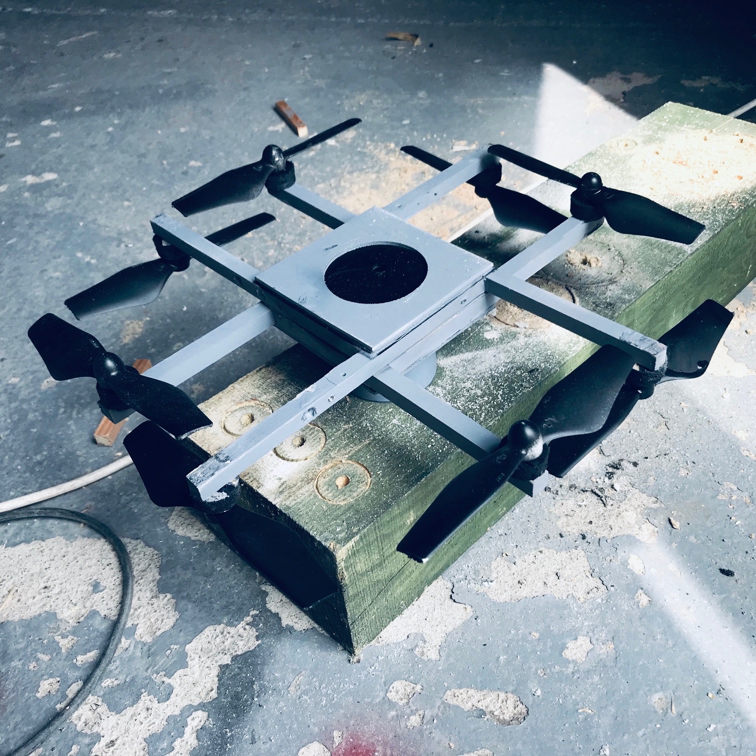
It thus appears that despite my aversion to under-slung motors there is an advantage in the arrangement in the photograph, in that it increases the gap between the propellers without adding to the overall depth of the airframe.

I also recall a research paper suggesting that increasing the gap between control-rotating blades increases the thrust ~ I guess because the efflux from the upper disk has more time to contract, to provide a greater volume of 'fresh' or unaccelerated air to the lower propeller.

The scale is unchanged from the previous at 1:5 and still features the 50cm square deck and 100cm spars, to which 32" propellers are attached. The motors have been reduced in size after I check the specs and see that they are only 10cm or 4" in diameter.

The hole is just over a foot wide at full scale and designed to accommodate a pilot-operator, although there is no reason why a powered rig of this kind could not be incorporated in the outline of a 'flying phone-box'.

Priority is to get it built, including the aperture, and give it a whirl.

Friday, June 28, 2019

8 Up


Here on the right at 1:5 scale a glimpse of the methodology to be used in order to comply with the GoFly challenge single-point-of-failure strictures.

The pair of modules at left are 'handed' and can include an aperture (or apertures) for where they need to travel up the verticals of an airframe, or the outline of a pilot operator.

They could be arranged back-to-back to form a quad-type octocopter, or else as here to form a true octocopter.

As conceived the upper set of motors were to be top-mounted on their cantilevers and the lower bottom-mounted ~ the value of modelling at scale however is it provides alternatives and this is one I like the look of.

It features top-mounted propellers throughout, which does great things for cooling beside reducing the vertical extent of the framework.

Also the frame does not then rest on the props whilst on the ground, while finally it means there is altogether more clearance between the rotor-disks and the lower torso, which may be a benefit should weight-shift prove a practical mode of operation.

In terms of dimensions these are are 32" props set on 20" square frames of 2" depth apiece, roughly modelling the T-Motor U13 power-units which are winging their way here.

Liking what I see, I'll probably forego bench-testing alternative layouts for the 'straight eight' appearing here.

For the aerodynamicists among you, the propellers that overlap actually rotate in the same sense... which means the blades that overlap are travelling in the opposite direction.

Though I drafted the original outline with an 18" deck to fit the competition guidelines, there remains room here to adjust the length of the cantilevers to suit the larger outline.

I'll try for a wearable drone in the first instance that can be steered by weight-shift, and see how we get on. To my knowledge there are no 'walkable' manned eVTOLs out there that can be steered by bodily displacement, and I like a challenge.

Beside which 'step-by-step' is my preferred means of execution.

Thursday, June 27, 2019

R-I-P


Last time I'll be making one of these I imagine now the parts have landed from China and we're set for the test-program at full scale. By way of a parting shot though this has been forwarded to the graphics guy to render as an update to the 'concept' shot on the original HeroX challenge pages.

And by way of a footnote the Bosch jig-saw died a death ~ fittingly ~ shortly after it was complete. It's been an old friend and travelled the world with me on various flying contracts. 

Had it replaced like for like today for £37 from B and Q... the king is dead, long live the king!

Tuesday, June 25, 2019

Woodwork Lesson


Experiment with wooden construction as promised. Redwood PAR of a nominal 2 x 1 inches section actually weighs 10% lighter than an equivalent alloy of 40 x 20 x 2 millimetres beside costing a quarter of the price. It seems to be as strong, especially cross-braced by trusses as it is here... nonetheless am still likely to run with an alloy build albeit with a foam sandwich in the centre-deck.

Meanwhile I continue to grapple with the allowable dimensions for the fly-off in order to accommodate a form of 'phone-booth' for the passenger, though I believe I have a solution.

Sunday, June 23, 2019

2-4-6-8 Never Too Late


Have to start prototype construction tomorrow, as far behind schedule as was my university thesis, and there have been two significant developments.

The first is that due a re-casting of what is going to be happening inside the square outline that you see above, its dimensions have reverted to those I used at the very outset, which is so often the way: it's called a hunch.

Secondly I realise that for some way into the testing at full-scale I can probably proceed with a wooden frame. This sounds outlandish in a world where everyone else is slavishly pursing CAD renditions of prototypes for three-dimensional printing of parts or else construction in carbon-fibre.

It has a few things going for it however.

Firstly, short of materials during WW2 both the Germans and the British retained wooden fuselages to produce aircraft that were among some of the best-performing of their day.

Secondly, even when jet fighters got into serial production following the war, they retained wooden parts among their structure.

Thirdly, the young "Real Life Guys" in Germany who've done as much as anybody to advance the course of manned drones have used wooden frames as often as not at the outset, and recommend so doing.

Finally, I've made some of these frames myself at working scale and they've proved as robust and rather lighter than the first full-scale mock-up (in 3mm alloy) which appears above.

(If there's a measure of success in all of this, however, it's the one most likely to appear in a museum.)

And where did the "8" come from? Well if this were fitted with 36" propellers at those axes spaced 60" apart, then the diameter of the aircraft at its widest would be eight feet.

Saturday, June 22, 2019

S-Team


Not all about work and make time for a vintage rally in Cheshire now the sun's making a rare appearance this summer. The performance of these things is in many ways improved by their weight, which adds to their traction, and this is welcome relief from working on a project that requires the lightest possible implementation of materials in order to get off the ground.

Thursday, June 20, 2019

Room for One More on Top


Honestly thought the models had been set aside for the duration but following further sleepless nights trying to reconfigure this in my head I'm beginning to see a way forward.

To recap, the original concept as submitted to the GoFly challenge featured propellers around both the dome of the passenger compartment and its base. These proved to be well outside the available dimensions for the competition and since then smaller motors along with propellers of a reduced diameter (32") have been ordered from the supplier.

This has re-opened a number of possibilities as regards the final design, which you can see beginning to take shape here. Anyone formulating an eVTOL vehicle will have found as I have that the final result is one of compromise among competing design requirements.

The second set of propellers will indeed be attached to the base and not the capital (though longer term a third rig could be added there) and one reason for this is that it also provides a wide stance for the undercarriage... a hazard with all vertical take-off types is a proneness to tipping that has to be obviated one way or another. Conventionally it has meant substantial skids, for which there should be no need here.

I have to get a dome 3-D printed for this fifth-scale model and add the second quadcopter besides a base, and thereafter it will be photographed and mailed to the graphical artist in order to be rendered for the benefit of the website.

Then I'll need to mock up the chassis in timber too satisfy myself with the ergonomics before pressing ahead with the build in alloy.

Famine or feast in this business.

Wednesday, June 19, 2019

19-JUN-19


Having ordered the parts I re-examine the prospects for my original concept in the form of a flying phone-box, for it remains just that:

Original.

As a captain I've been used to an alternate and a destination and we have the luxury in the coming weeks to review each upon its merits.

The original 'flying phone-box' as seen below was discounted from the GoFly challenge for exceeding the dimensions, which are allowed only 102" in any radius measured from any one point to the farthest distant.

Looking at the outline draft above it appears that this can be mitigated, for using this outline 32" propellers might be separated vertically by up to 52" assuming a planform of 84" square.

(In fact for a child-sized passenger compartment the power-rigs might still be located at top and bottom.)

Nice thing about it though is the fact it runs on sliders, or vertical columns to which each quad can be attached at any level, providing the maximum leeway for flight testing.

They can also be stacked directly one above the other, or else offset as seen previously in the 'wearable' outline.

My rule of thumb however in pursuing any prototype is whether I find the prospect exciting. 

And frankly I do ~ so could the phone-box be set to take off after all?

Tuesday, June 18, 2019

Cold Draft


What might have been?

Received the draft from the graphical artist for the contra-rotating outline with the 40-inch lower set of propellers and 36-inch upper.

This has been dropped in favour of a more conventional octocopter layout bearing smaller motors, though it went to the (figurative) wire.

This is principally an effort to err on the side of safety, as it runs at a lower voltage and turns 32-inch propellers which are more evenly-spaced, whilst farther from my own dear flesh.

Will never know how they compare without testing both types, which is an expensive notion.

Time waits for no man meanwhile and as the debate quietly raged the supplier augmented the power-units above, that generate 35 and 20 kilos of thrust respectively, with altogether larger combinations producing 100 kilos apiece.

They're five times heavier than my motor of choice (the U13) and prohibitively costly too, though.

Anyhow, should have some shiny toys to be playing come the month's end.

Sunday, June 16, 2019

Double Whammy


Been brought to my attention that there's a lot of competition out there, administered by YouTube in the form of death by a thousand cuts. 'Twas ever thus, however, and when Shackleton set off for the South Pole he was not to know that Amudsen would arrive first. Explorers are rarely the type to give up before they've even started.

Recent weeks have revealed that the outline of the 'wearable' drone I proposed to use was, strictly speaking, the subject of a patent specification filed by a German technical university and the flying machine above is the result of the efforts of another university, based in India.

I am not so much bothered about the extent of the intellectual property so much as my own intellectual prowess in all of this ~ not so much the being smarter than the being original. In fact the career advice for my own life could have been the same as that provided the manager of the Sex Pistols whilst still at school... if you're going to fail, at least do it in style.

Strictly speaking too, nobody has yet to my knowledge either patented or flown a truly wearable drone viz. one that is essentially two-dimensional and that can be supported on the ground unaided and wandered about with.

This week therefore we have to online an experimental program that will encompass the most likely to earn us some form of lasting recognition and a commercial product to boot.

It is likely to either to remain a truly mobile drone not altogether dissimilar to the one above (and all credit to them, for every one of these represents a personal Everest for someone or other)...

... or else a top-mounted multi-copter of the kind I had in mind before people suggested that it was likely to be insufficiently manoeuvrable due to its overly pendulous stability.

Examining the myriad efforts again on YouTube, some people have made a success of conventionally mounted rotors and not least Volocopter: the king of such types. Others, not least the talented German brothers who managed to get a bath-tub airborne, have found the type as insufficiently manoeuvrable as I was advised.

Most confusing is the fact that in all of these efforts, a tweak to the software has sometimes rendered the wildest steed as docile as a seaside donkey. I like the home-build below, which was only ever intended for hovering around the back lawn and does so with some aplomb.

Bravo!


Tuesday, June 11, 2019

Answer's 4.2


The above iteration is about as compact as you'll get and could be driven practically straight into the garage... a true flying carriage only seven-foot square.

Ironically it falls foul of the dimensions laid down for the GoFly challenge, which are fixed on radials, upon which basis its maximum diameter exceeds the 102 inches allowable.

The eight-foot square iteration below has a diameter of only 100 inches, meaning that the competitive model may yet be larger than the commercial product.

But I cannot complain, for though it needs tilting to get it out the garage it's altogether easier to build while being more aerodynamically efficient (because its overlapping disks feature only contra-rotating blades).

Although I am going on hunches, it's likely to be more efficient than any of the alternative configurations which feature stacked drones and will thus be submitted as the final draft.

But why is 4.2 the answer?

Because the alloy stockist retails 25 x 25 x 2mm sections in 4.20 metre lengths, and divided four ways (plus allowing for the cutting blade) this provides 41" spars.

Time to cut metal.

Monday, June 10, 2019

Ring o' Roses, We Don't Fall Down


The fly in the ointment for the GoFly challengers is actually safety. The go-karts we built as kids out of pram wheels and pallets wouldn't have met the road safety regulations applicable to the those we ran down at speed, and from the same point of view were I to be building one of these things to fly around a field it would have four large motors and four large propellers.

Such motors however are wilfully overpowered if they are going to be doubled in number to satisfy redundancy requirements, which is a pity because all aircraft evolve into types with the least number of power-installations that still satisfies safety. Thus jet airliners devolve into twins, and helicopters most benefit from two engines driving the largest rotor.

Drones are a little different, for while there are tri-copters out there the structural simplicity of quads tends to make them the more popular. All design is a trade-off and there are good arguments here ~ though there can't be many teams still drafting final outlines ~ for using more motors driving 32-inch propellers.

A benefit of my underlying outline is that independent modules can be stacked ~ at an offset as above or coincident as below. The first is more aerodynamically efficient, the second more structurally efficient. In both cases though the safety margin between my body-parts and the rotating parts is thankfully greater.

I've always been a structures man whenever a choice has to be made, as now when the time for spending hard-earned cash for equipment is upon us, so we take forward that one here:

Tuesday, June 4, 2019

Star, Trek


I mail Trek Aero after all, seeing how the eight ducted rotors featured in their 'Trek 1' would appear adaptable to the layout of the wearable drone (as per recent post). They are however fully occupied with prototyping a client's vehicle beside their entry GoFly's challenge.

In view of the number of projects clamouring for large EDFs or Electric Ducted Fans, it seems they hit pay-dirt.

For all their drawbacks however free props offer advantages too, so I'll stick to the knitting.