Wednesday, March 9, 2022

60" Build Step #25


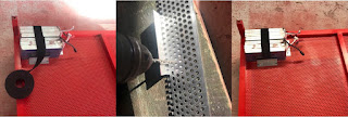
This is what I mean. Here a typical pairing of 22.20 volt six-cell LiPo battery-packs are set in the forward left corner of the air vehicle, with the cables set to address an ESC positioned nearest the motor to be fixed centrally upon the perimeter tubing seen top of the photo. Wrapped round the packs is velcro fastening tape to size the battery tray  formed of two off-cut lengths of angle-alloy.

The brackets are marked to show how they line up with a row of perforations, so that a couple of holes can be drilled to house the pairs of pop-rivets that secure them too the safety grille. Afterward two short lengths of velcro tape are riveted to one of those brackets, beside the perimeter tubing itself. You may wish to drill and fasten the latter length of tape PRIOR to fitment of the corresponding bracket opposite, so as to make room for the hand-drill.

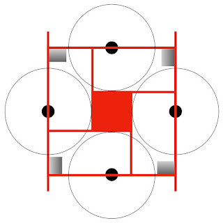
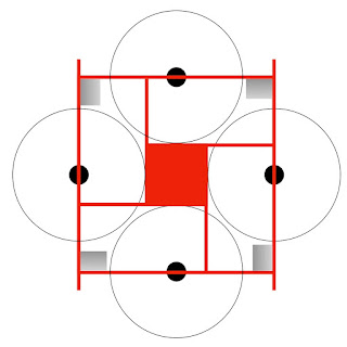
As with most operations during this build, repeat a further three times. Battery-packs are located in these positions principally because it's much easier to support their weight when they are placed on the top-side of the airframe than suspended beneath. They are also set at a distance from the pilot-operator, so that the risks associated in (a) connecting the batteries whilst clear of each propeller's arc and (b) fire during their operation is reduced to a minimum.

It also distributes mass evenly around the airframe, albeit at the expense of reducing the manoeuvrability by the same degree due to dispersing it furthest from the C of G: as ever then it's a case of 'Keep it simple, stupid'.

Sunday, March 6, 2022

60" Build Step #24


Slight re-jig on the battery placement to accord with the likely wiring layout. Packs will be joined in series with the built-in connectors, and in turn the remaining positive and negative will supply the ESC (electronic speed controller), which in turn connects the motors in the same way.

The ESCs have each to be connected however to the centrally-located flight controller, and this will be via the four arms extending from that section. The end of each arm thus forms a T-junction where 50v wiring from the battery and the 5v from the avionics bay are joined together.

The planned location for the battery-packs have therefore been moved to that corner nearest the associated arm. Accordingly looking at the diagram the pack at top left is designated #1, and then through #4 going clockwise. The associated motor to the right of the first pack is also designated #1 and turns clockwise direction, as is conventional with a quadcopter; the remaining sequence runs anti-clockwise (#2), clockwise (#3) and anti-clockwise (#4).

Avionics continue to occupy the underside of the centre-section, allowing for the fact that a passenger stood upright might be as accommodated as well as a seated might.

Saturday, March 5, 2022

60" Build Step #23


We're at the point where we have to decide where to dispose of the battery-packs and we shall put them here basically because we can. It unloads the centre-section, which is already carrying the weight of the passenger; it also allows for a safe approach from each corner in order to connect each power supply while remaining clear of propeller; and it avoids the need for a central bus or distribution board with the messy soldering which that would require.

The batteries in the diagram show the dimensions of a typical pair of seven-cell packs of around 22000 mAh wired in series to produce around 50 volts, together weighing in the order of six kilos (thirteen pounds) per pair.

Thursday, March 3, 2022

60" Build Step #22


Sit on the chair and take a break, as you deserve it. Note use of ply airbridge to avoid NO-STEP zones when boarding. The grilles upped rigidity so there's barely a deflection due to my seventy-five kilos (twelve stone... shit!) and bear in mind the motors will be flexing the airframe in the opposite direction and relieving the stress on the structure, if not the pilot.

Things we might do differently? We're up to 17.5 kg (39lb) in weight and we could have attached the safety grilles with brackets instead of angle-alloy, which would be lighter, cheaper and easier. I would prefer taller skids and horns too, but then the decision to mount motors on the underside came late in the day.

There may also be the option to reduce the frame from 60" square to 54", though I am waiting on T-motor for comparative performance of 36" propellers as against 40". The rule of thumb for rotorcraft tho' is that the greater the disk-area, the lazier motors may run. This in turn reduces the size of the battery-packs, which will lighten the load accordingly in a 'virtuous circle'.

The airframe is designed around T-motor's U15II 100KV unit driving 40" propellers that ought to produce up to thirty-five kilos of thrust apiece. It's not unusual to suit the airframe to a projected power-plant at the design stage, incidentally, as there's always an element of symbiosis there. Next task ~ Rome not having being built in a day ~ is  to fit the motors along with the avionics and sub-seat battery-packs.

60" Build Step #21


For flight-testing I've selected IKEA's 'GUNDE' pilot-seat and ejection system. The seat costs £9 here in the UK, though supplementary ejection-pack 'AARGH' costs an extra £90,000. Taking your nylon 20mm conduit cable-clamps, pitch these just inside of the IKEA-supplied plastic feet (which form a nice abutment).

With these saddle-clamps in place, locate the seat entirely centrally for reasons I've yet to fathom. Draw around the clamps with a sharpie or scribe, and remove so as to drill a 4mm hole through the depth of the centre-section. Avoid the use of pop-rivets at this stage if you value your life.

Park the frame against a garage wall and fasten using both washers and 'nyloc' nuts... for which you'll need a 7mm hex ring-spanner. An aid to this process is an off-cut of 20mm tubing that keeps the clamps aligned during fastening. It proved not to need a cross-head screwdriver on the other side, for reasons best known to the fastener. An easier alternative again however is to do this prior to fitment of the safety grilles.

There's a message here from the FAA inspectors following our build-process in lock-step:

We cannot believe that you seriously contemplate using a $12 chair from IKEA for the purposes of flight-testing. Are you unaware of the fact that Walmart do a camping chair for only $9.99, which INCLUDES drinks-holders?

Wednesday, March 2, 2022

60" Build Step #20


A moment to congratulate ourselves, with the safety grilles in place. These are around 19" wide apiece and broadly tailored to fit, although the 1" margins allow for significant slack. I have pop-riveted the grilles in place at sixteen points that correspond with those used to fit the angle-alloy strips.

The airframe is rather harder to carry now in view of the fact you cannot step inside of its perimeter, but there'll be a fix for that in due course. I recommend fastening all four grilles in place however as they add significantly to the overall structural rigidity of what is after all, a beta-product.

These surfaces will adequately support hand-tools and so on but are 'no-step' zones as regards boarding the aircraft. A top tip is a 19" square outline of half-inch plywood to form a temporary 'air-bridge' for boarding passengers: NO STEP decals and a white silk scarf are a must for the pioneering aviator at this stage of the game.

This the last 5mm-perforation sheet before the supplier needs to re-stock, at a price uplift of over 40%. The product is from Germany (a reason for its metric size), though the ore from which it is made comes from... Russia.

Tuesday, March 1, 2022

60" Build Step #19


Here's what I'm getting at: I've purchased two six-metre lengths of 1" x 1" x 1/16" angle alloy, cut into three equal lengths to fit the car. Back at the workshop the question is to whether we shall mount the safety grilles flush with the top-surface of our frame, or else level with the underside. For practical reasons the latter wins out.

Proceed by working with the long lengths arranged around the outside perimeter by clamping them in place and driving in five rivets: one at each end, one centred and two more centred again between the first three (and all done by eye). Take care not to locate the end-rivets too near the internal tube connector, which projects around two inches.

Next do the same with the internal long lengths, for which you will need to remove the bolts that secure the four cantilevers to the centre-section. Mark the location and drill a hole in the angle alloy to re-fit the bolt. If necessary mark up those rivet-heads that may be in the way with a touch of paint so as to make an impression, and drill an oversize hole in the angle-alloy to accommodate... it's what prototypes are there for. Only four rivets needed here as the bolt serves as the fifth.

Finally add the shorter lengths, using three rivets to secure. I have not mitred the join between long and short lengths of angle-alloy because (a) it wastes material and (b) I cannot be bothered. As a result the short lengths are a couple of inches shorter than you might have expected. Measure all lengths independently too, as they may vary just a little depending on how true the original rigging of the centre-section had been.

The net result however, as you can see, is four trays into which our safety grilles can be dropped tomorrow, which after all is another day. We will need an elevated cockpit as such times as eight motors are incorporated in X-8 configuration, though here we're building a utility quad for those 'low-riders' amongst us. Accordingly we can set it all on the level, and this is the safest and most practical way to do so.

60" Build Step #18


Essential to the process of prototyping is revisiting the fundamentals as it appears the existing structure will support my own weight along with that of the IKEA folding chair. As a result I shall dispense with an additional layer of complexity in the shape of a separate flight-deck and instead run with what we have, and fit the motors underside.

This is also because the perforated sheet is supplied at 1000 x 2000mm, so that if it is divided four ways width-wise it produces four safety-grilles to fit round the chair. Each of the spaces surrounding the chair is practically a metre by a half, which will as ever minimise material waste... less always being more in this game.