Monday, February 28, 2022

60" Build Step #17


The frame largely complete I turn my attention to raw materials for the 'clip-on' flight-deck:

    (a)    483mm (19") x 2000mm x 2mm aluminium sheet, 5mm perforation.

    (b)    1524mm (60") x 20mm x 2mm aluminium round-tube, 2 off.

    (c)    1460mm (57.5") x inch-by-sixteenth aluminium square-tube, 2 off.

    (d)    inch-by-sixteenth aluminium square-tube off-cut from previous.

    (e)    square-tube M6 threaded inserts, 8 off.

    (f)    20mm saddle brackets, 8 off.

    (g)    20mm round-tube inserts, 4 off.

    (h)    white primer and Post Office red paint.

The big-ticket items here amount to £117.60, though bear in mind that at the height of the Covid-19 pandemic perforated sheet alone cost as much as £1000. This brings the total however to £314.23, so this flight-deck better be worth it. The inclusion of 20mm tubing at this stage can be explained by the fact that it is a regular electrical-conduit measure for which clamps abound. Our vehicle is to be a commercial-off-the-shelf (COTS) work of art. 

Friday, February 25, 2022

60" Build Step #16


It's time for me to put the skids beneath you, though actually they're not so much of a necessity as they are with conventional rotorcraft (which have occasionally to land carrying forward speed). A power-failure in a quadcopter is a crash-landing while the same in an octocopter need not require a forced-landing at all. What neither can do in any event is to glide or 'autorotate' to the sort of landing that requires upturned skids.

What I have used here is the same spec of tubing used at the outset, and joined with a T-shaped 3-way tube-connector to stubs of four inches, capped with domed inserts. Assemble all parts of the skids first before sliding them onto the undercarriage legs, making sure that the inserts (which are domed in one direction only) are facing so that they provide an upward curve like a ski. Ensure too that the kitchen-cabinet brackets are set on the inside of the frame relative to the orientation of the skids.

You may wonder why we add stubs at all given that they require 3- in place of 2-way reinforced connectors, with their extra weight? This is clearer from the central image, showing how it allows the airframe to be set upright without resting on the motors or propellers which overhang the frame.

The stubs do at least provide a hint of helicopter and indeed could be extended at any time with horns  by using angled tube-connectors in lieu of engineering. They also assist in orienting the aircraft under radio-control ~ ever the issue with quadcopters. Set in either direction, too, they provide mounting-points for a wheeled undercarriage.

The skids, paintwork and rivets add £77.30 to the build and raise the total to £196.63, not counting £8.99 for a new pop-riveter plus the cost of driving to Barnsley to collect the parts. The assembly weighs 8.80kg: 20 pounds of airframe for 200 of your sterling.

Flight-deck next, but don't hold your breath.

Monday, February 21, 2022

60" Build Step #15


I've combined that Insta-opportunity with a shake-down for the transport operation, as it invariably yields setbacks like loosened bolts, saturated avionics or grit-ingested motors.

You also get a good look-and-feel for the portability and ergonomics of the thing, plus much else. For instance here in this Force Eight gale you could feel the harmonics as the frame began to sing, and a key factor in digital flight-control is the adverse affect that this can have on stability (tho' the test-flight in December appeared satisfactory in this regard). Also, heaving this through the dunes I felt it's as big as you'd want to be toting around on your person.

It was also remarkably stable given the wind conditions, regardless of the house-brick that was only put there for scale. It also shows that helicopters have skids principally to avoid sinking into soft surfaces, and I may adapt the legs to snow-skis in due time.

Before then though we'll look at options for fitting a conventional skids, tho' not until next week... I've some living to do here meantimes too.

60" Build Step #14


Here by way of a recap the tried-and-trusted fix for tube-inserts, except for the upper posts a single rivet will do because these are going to bear the load of the flight-deck and I've no plans to be flying inverted at this stage. The undercarriage legs a different matter however as they're subject to loads in various directions during flight operation and road transport.

Incidentally there are of course proprietary adhesive-fillers much like silicone, though these are a one-way street whereas using silicone (and once the rivets are drilled out) you don't have to be King Arthur and his Excalibur if it comes to re-jigging prototypes. For instance we always have the option prior to flight-testing to alter the dimensions of these corner-pieces, and in fact for a beta-product I like the idea if them ALL being the same length of only to reduce the parts-count.

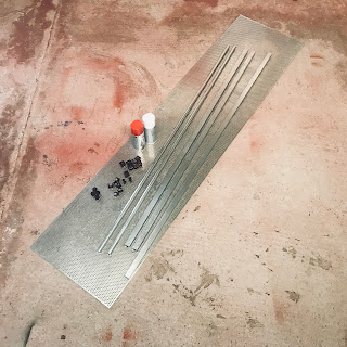
After a little to and from in the head however I have elected here to use whatever I've left in the 'shop in the way of off-cuts and this has resulted in posts of 4" length and legs of 7". This is quite nice as it makes (including the depth of the tube-connectors) for a basic airframe that is exactly five feet by one. The Europhiles will be wondering if ever I am likely to publish in millimetres, but propellers are the starting point here and the Western world still uses inches for these... so start as you mean to go on.

(This is not exclusively so, for 25mm and 1-in parts are broadly interchangeable for our purposes here.)

Note too that the undercarriage legs are braced laterally by kitchen-cabinet brackets. (Always ask your local shop for aviation-grade brackets, along with a long weight and a sky-hook if you're new to the project.)

Finally all aircraft have at the outset to consider the logistics of ground operations, for which the key here is my one- by two-metre flatbed trailer. We could go smaller on the frame with 36" propellers, but this would mean it wouldn't clear my wheel-arches. At the same time it's looking like the motors are going to be top-mounted as it makes trailering  altogether simpler, beside upping the ground-clearance that we looked at in the previous post.

On the other hand nothing in life is for free, and that does mean that the flight-deck may yet need to be raised a little higher on those corner-posts as there is just an inch of clearance at present, which is tight even for those carbon-fibre freaks amongst us.

Sunday, February 20, 2022

60" Build Step #13


This is where having been an airline captain for so long does help. To the studs we've added 4" posts on the topside which will eventually support the flight-deck, whilst on the underside I've added four off-cuts to form legs of around 13" length. All of these include M6 threaded inserts as previous, in order to mount skids and a flight-deck. 

The posts up top need be a minimum of 3" incidentally to allow for those threaded inserts beside 2" for the actual stub. The lower legs intended to support the skids will  be reduced to nearer 9" or 10" however, a length based on a combination of both flight and structural requirements. The legs are the Achilles' heel of the construction, not so much fore and aft as regards side loads imposed on them and though steel-reinforced they may yet require pressed-steel brackets as well.

During take-off and landing maneuvers a bank-angle warning is a commonplace with airliners, the 737 for instance risking an engine-scrape during crosswind landings. As the primary flight instrument is calibrated however in tens of degrees, bank angles of say 25° or 35° are unmarked. As a consequence I have targeted 20° as a mark beyond which 'there be dragons' for the incautious pilot during those critical phases of flight.

The 40" propeller is suspended 3" by the underslung T-motor U15 and so we need to add that to the clearance calculation (though the skid-connectors will provide an inch and a quarter toward that). Meanwhile as the propeller projects 20" from its axis, then 20" and 20° is a memorable combination of figures. 

The calculation on the right of the picture calls for 7.25" from which we subtract 1.25" for the skids, however, so that we need a 6" drop and 3" to allow for the displacement by the motor: this therefore requires undercarriage legs of around 9" apiece.

I may drop that to 8" or increase it to 10" instead, depending on how I feel on the day...

Saturday, February 19, 2022

60" Build Step #12


Without the benefit of California temperatures (and in view of painting requiring one of at least fifteen degrees centigrade), whilst you cannot always raise the temperature in the workshop you can still bring the frame indoors for a heat-soak prior. I recommend use of a white primer too as it guarantees the colour of the final coat. All in all then, a good day's work.

We're pushing boundaries here with a choice of 1/16th alloy section and prior painting, standing my 77 kilos on the centre-section it flexes by around an inch. Aircraft do flex, but ideally not to the point of failure. It is unlikely tho' that we shall be able to load a seat, passenger and battery-packs on that centre-section without the shock-loading of a heavy landing causing such a failure.

We shall see then subsequently how the 'clip-on' module in the shape of a flight-deck will also pitch its weight mainly (or exclusively) on the four corner-points, transferring those loads directly to the undercarriage ~ one benefit of the flexibility of our design.

60" Build Step #11


This step is a purely self-congratulatory photograph now we've completed the first module of three (viz. airframe, flight-deck and undercarriage). A benefit of the modular means of construction is that you can pay as you go. Another is that it can be stored surreptitiously among the other detritus lodged in the garage: "What helicopter, dear?".

60" Build Step #10


You can see that nicely from the first of those pictures, where we've turned one of the edges through ninety degrees with the tube-connectors secured, and slid it into place. Note that the other side awaits the same treatment.

The only reason for attaching lengths in opposing pairs in this way is that the central section is bolted in position. Releasing these bolts allows for sufficient flex to apply the tube-connectors one by one, if this alternative method makes you any happier.

This done however we can park the airframe upright and bang in those extra rivets with the assistance of G-clamps. I have put a perimeter squeeze of silicone along the edges of the foam insert prior to capping the centre-section off and this final pressure will likely squeeze some out from around the edges.

All that remains to do now is to draw-file its rough edges and finish with a little emery   cloth and the assembly is ready for a white undercoat and a shiny finish in Post Office red prior to an appearance on Instagram.

60" Build Step #9


With the centre-section assembly complete, lay out the parts on the workshop floor again so as to size up the assembly mentally. The component parts of even the Titanic were once chalked-out on the workshop floor; and look what happened to that. I have called on a set of weights to secure the arrangement in position during this process. Knew I'd have a use for them eventually.

With this done, mark up where the bolt-holes will have to be drilled again in order to attach the centre-section to the perimeter frame. An advantage of square tubes over any other is that you cannot make a mistake doing this as they can always be turned through ninety degrees.

Entering stage right now are our the four-way tube-connectors, and there is only one way these will lie flat on the floor (which is technically the wrong way, reason being that we're going to want to terminate each corner with upward- and downward-facing stubs).

What we do here then is to secure a pair of connectors into only the lengths of tubing that are going to form opposite sides of the 'square' so we can slide them into place at a later stage. Make sure when you do that therefore with the previously-drilled hole where you want it to be when you've turned each length through ninety degrees to fit.

Finally beside the inevitable squeeze of silicone, rivet each connector in place during.

60" Build Step #8


This is a cheeky little phase in construction because it calls upon a material which is strong in compression and also in shear, in the form of a low-density insulation foam. The benefit of this is that it is available off-the-shelf, albeit rarely intended at your local DIY store for flying machines.

One way of cutting this to suit is simply to place it about where it's going to be and just knick the edges with a Stanley knife before using the same tool and a yard-stick to eventually cut the panel to size.

Then flip the frame over (note the right-pronged appearance) and apply a silicone seal around the edges before squeezing the foam into place. When you do this, spread the weight gently and evenly so as not to crack the foam within its foil-backing.

You can see that we are good to go from the last picture, whereupon we rivet the next sheet-alloy square to form a cap on the underside.

60" Build Step #7


With the arms teed up on that back-plate, use a 10mm (confusingly that drives a 6mm shank... it's all about the head-size) box-spanner to hand-tighten the joints. Normally I save the final twist until the assembly is complete, as it provides for a little leeway for the inevitable jiggery-pokery involved.

I just realised too (or else I'd forgotten from previous, which is one benefit of sharing knowledge among the matrix) that rather than slip out that template from underneath we could just have used the second of the pair of sheet-alloy squares to place on top.

What I did again here tho' was to slip that square out from beneath and set it up on top with the benefit of the set-squares to keep things true. When I say true, we're not working to microns here because ultimately it doesn't matter: unique amongst the designs of flying machines drones are simply self-levelling devices that don't care as to how and where the various motors and propellers are mounted.

With things broadly looking just-so, therefore, we hammer four more rivets around the perimeter to hold the top-plate in place. With this done we can all relax, maybe over a cup of tea. Then add a rivet in each corner, being careful to avoid the internal bolt else removing each one temporarily to allow. I generally then add a fourth and fifth rivet at each side, though this can be done at a later stage once the general outline is secure.

60" Build Step #6


Around the side of those stickers we've used an arrow so as not to mark up the wrong side of the tape. With that done I've taken an off-cut of 1" tube and marked out the width of the joint, using the same straight-edge to mark an 'X' for the centre-punch.

I may be teaching granny to suck eggs here, but of you want to be super-accurate you can drill from both sides in the absence of a power-pillar drill, which I've given away. I trust to my own judgement and go in from the top with 4mm pilot-hole. This usually results in an off-centre hole on the other side of the tube, but then I go in from the backside with the 6mm drill-bit (that matches our hex bolts) so that I can lean on in the hand-drill in the required direction to centre things up.

60" Build Step #5


With that centre-section flying free as a bird now on the garage floor, we've raised the sheet alloy and using the pencil-marked margins lined it us as-good-as with the four arms. At this stage we apply a length of masking tape to mark where these cantilevers will need to be drilled, and at the same time numbered them viz. a viz. where they are going to end up on the 'drone. Handily, the film backing on the sheet metal includes an arrow that we can use here to remind us of which way we will be headed.

It does not really matter whether the airframe is going to be flying 'left foot forward' or whether you're what the snowboarders call a 'goofy rider'. At the end of the day it is down to whatever floats your boat... or drone. Note that both the cantilever arms and the sheet-alloy are numbered up.

60" Build Step #4


It's time to get jiggy with it, and we've turned to the longer lengths of alloy here so as to arrange them four-square using a set of, well, set-squares that do what they say on the tin. Note that the ends just kiss each other rather than overlap, because the tube connectors will go that last mile. Well, inch actually. Looking at the image at centre it can be seen that I shot myself in the foot with that 38.125" measure for those shorter lengths, forgetting the overlap.

I've taken an inch off all round however and note that in the final picture the parts are laid out to my total satisfaction and set upon one of the two 19" sheet-alloy squares. Finally note that we should mark the margins of that centre-section with a pencil as a guide, as we are about to slip it out from under there and place it up top ready for the riveting.

60" Build Step #3

N.B. THE FOUR ARMS SHOULD HAVE BEEN 37.125" INSTEAD OF 38.125", SHIT HAPPENS.

Well with that out of the way, let's move on to construction of the 'drone itself and we start by taking those arms and applying a squeeze of silicone around the inside edges of all eight ends before tapping in the threaded M6 inserts... from which I have to say the average fabricator will draw a practically sexual satisfaction (or at least until those rivets are driven home).

I've opted for 4 x 12mm pop-rivets as a good all-rounder, and a 3.9mm drill-bit offers the tightest fit, although I've gone for a 4mm bit as it is available on any desert island. Apply those rivets to opposite sides as a belt-and-braces fix, and we'll see later that these opposing pairs need to be oriented methodically during assembly.

Airworthiness inspectors might question whether this meets required tensional specs and should this be a sticking point. Offer to hang them from the rafters with the same method and if the joints prove to be up to scratch, then you're clearly the winner...

Thursday, February 17, 2022

60" Build Step #2


There are three modules to the 'drone viz. airframe, flight-deck and undercarriage. The reason for this is that like the containerised transport system, the design features a four-cornered means of connection forming the basis of a modular system that offers (a) choice of undercarriage whether skids, floats or castors (b) choice of payload whether seat, stretcher or cargo-box and (c) choice of four or eight propellers.

Altogether, you're spoilt for choice. We'll first build the frame to which flight-deck and skids will be attached, the recipe for which module includes the following:

(a)    4 off 58" and 4 off 38.125" by 1/16th aluminium square tubing, cost £36.47

(b)    2 off 19" square 1.20mm plain aluminium sheet, cost £32.40

(c)    4 off 25mm four-way steel-reinforced tube connectors, cost £44.19

(d)    8 off 25mm square 6M threaded inserts, cost £5.87

(e)    8 off 6 x 40mm hexagonal bolts at £0.40

(f)    Total metal/plastic parts airframe, £119.33

That's just half the cost of lunch at a Michelin-starred restaurant, and you can't share that. Leave those ingredients indoors overnight, as warm alloy is more workable.

Wednesday, February 16, 2022

60" Build Step #1


Pays to draft the outline at the outset and I've done so in Apple Pages, whose elements a chimpanzee could grasp. I am actually old enough to have worked with the Vydec dedicated word-processing system that could output text to the printer for an equivalent outlay of $60,000... so Pages is rocket-science so far as I'm concerned.

I like what I see, a caveat being I may stretch the central square to 50 cm instead of 19 in (because the sheet-metal supplier does so in metric).

Going to be a leisurely build, but I'll hold your hand throughout.

Tuesday, February 15, 2022

Go Big, or Go Home.


Few people watching the 2022 Winter Olympics will be aware of the significance of the name, but Jake Burton effectively invented the snowboard, or indeed the sport of snowboarding. Like every other groundbreaking development, most or all of the parts were already there to the extent that what remained was ~ as it had been with every other form of locomotion ~ for someone to come along and demonstrate the possible.

What the HBO documentary Dear Rider makes clear, however, is that the earliest years were in the words of the inventor, decidedly lonely as he investigated various forms of manufacture and shipped in dozens a product that would come to be sold in millions. In truth, the sport never really took off until such time as he collaborated with a small ski manufacturer in Austria called Kiel, who could apply conventional fabrication when every other ski manufacturer had dismissed the notion of the sport going mainstream.

There are parallels now in the polarisation between moneyed air-taxi developers and the comparatively impecunious of personal air vehicles. But what developments like the snowboard demonstrate is that the public at large rarely see which of them might succeed, except in retrospect. Donating prototypes to museums has therefore closed one phase of development, yet at the same time calls for the next.

For what is life after all, without a project?

Friday, February 11, 2022

Nothing Ventured...


I donate the second of the prototypes to Aeroventure, or South Yorks Aircraft Museum in Doncaster  based on the site of the historic airfield... a place where, for instance, all of the wartime DC-3 Dakotas were modified for use by the RAF (to right-hand drive?). 

For me though in the late 1970s it was a place beside the race-course that the crew-bus passed by enroute to Finningley. Each airfield was established by the Royal Flying Corps in WW1 and are thus amongst the oldest in the UK, if not Europe. On a more modest scale altogether it was where I first took to the skies myself: at the controls of the venerable Bulldog and alongside Squadron Leader and Spitfire pilot, Ron Brown.

Like so many exhibits this is a sum of its parts, its duplicate in the Helicopter Museum bearing the original airframe, and this the motors and propellers used in that test-flight of December last year. I like the fact it hangs here from the ceiling, and in the very best of company in the form of Bell's 47.

Sunday, February 6, 2022

Enstrom Ending?


Appears Enstrom ~ a company as old as myself ~ is yet to rise from administration like a phoenix. The company was started by someone with no knowledge of aeronautical engineering, but ample enthusiasm (which gives us all hope). But it was the steed of choice for Dennis Kenyon, who passed a year prior to the demise of the company.

I've chanced upon some remarkable pilots unknowingly in years past. One an old man whom I used to pass with a cheery greeting outside the hangar in Bournemouth we were both frequenting whilst he was flight-testing a single-engined turbine aircraft. It turned out to have been Neville Duke, one-time holder of the world speed record.

Dennis I also shared hangar-space with whilst scratching a living a fixed-wing QFI. He returned to flying helicopters later in life from necessity, and for the same reason most men of advanced years with whom I once shared a cockpit did so: divorce. But I witnessed one of the most heart-stopping aerobatic displays I have ever seen, before discovering only now ~ some thirty years on ~ that it was a world champion that I was watching.

I recall how telling me that to refine his craft on the Enstrom they would fix a strip of balsa on the tail-boom to see how close during maneuvers the main-rotor came to slicing through the tail-boom.

We shall never see his like again... or theirs.

Thursday, February 3, 2022

Room (for) 101


Added to the hundred existing artefacts in the world's largest collection of helicopters is the fifth of our prototypes, as flown back in the first week of December of last year. And here in the foyer the proprietor himself in front of the oldest surviving helicopter in the world in the shape of Hefner's Revoplane. The cost of this was underwritten by a British cotton millionaire, doubtless derived from the industry in Lancashire... that great seed-bed of aeronautical development in the UK!


and blurb:

Among the many hundreds of experimental ventures worldwide in the field of ‘personal air vehicles’ or PAVs, the TELEDRONE was designed and built by Colin Hilton as a spin-off from his earlier entry into the Boeing-sponsored ‘GoFly’ challenge, which took place at NASA Ames in Silicon Valley early in 2020. 

The development of air vehicles of this kind was made possible by the digital control of increasingly powerful motors, alongside improvements in batteries and electronic components derived in large part from the mobile phone industry. Effectively a scaled-up quadcopter, the operation of this scale prototype by radio-control was possible by registering it as a regular drone ~ an avenue open in both the UK and US up to a weight-limit of 25 kilograms or 55 pounds.

Further development is possible in the UK at weights of up to 150 kilograms by special permission from the CAA, and thereafter at greater weights again under Experimental Category. Thereafter however regular certification would be required, which is a process evolved over decades and aimed at piston and turbine types and as such, prohibitively expensive. It is not the case in the US however, where in an effort to stimulate the development of ‘eVTOL’ types the FAA allows for such aircraft as this to be flown largely without regulation up to a gross weight of over 115 kilograms so long as there is a pilot onboard. Consequently TELEDRONE types like the one seen here will be scaled up to adult size in order to be pitched to the US market in the form of rapid kit-builds.

Technically the airframe comprises a patented four-pronged cantilevered structure to support the centre-body, whose advantage is that it is effectively a two-dimensional construct adaptable to conventional fabrication in aluminium. In the case of this latest version of the machine, however, this is bounded by a 48” square perimeter frame that extends to four undercarriage legs in support of either skids, floats or casting wheels.

In order to pack the remaining components as practically as possible, the avionics are situated on the underside of the central section, and comprise a radio receiver linked to the V-aerial at one corner of the airframe, beside a Pixhawk ‘cube’ flight-controller (to which GPS signals are fed from a disc-shaped antenna located at another corner). The controller is wired in turn to each of four ESCs or ‘electronic speed controllers’ which control the four 6 kilowatt motors digitally as ‘virtual’ AC motors albeit running off a DC supply. The supply itself is drawn from a pair of 22000 mAh battery packs wired in series to produce around 45 volts.

The prototype thus has an endurance of between ten and fifteen minutes, with each motor requiring only a fraction of the potential 100 kilograms of installed thrust required to support the gross weight of 25 kilograms. The test-flight was undertaken on the 2nd of December in 2021 at Frome model aero club on the Somerset Levels, with the wiring, tuning and test-flying pursued by Angus Benson-Blair. The subsequent development phase would see the airframe expanded to 60” square and powered by 10 kilowatt motors driving 40” propellers in pursuit of elevating a mannekin by radio-control and thereafter an adult pilot onboard using hard-wired controls.


Max Speed 63 m.p.h. (FAA Part 103 Ultralight limit) in ground-effect

Empty Weight         20 kilograms

Capacity         1 child

Power 4 x T-motor 5.5 kilowatt motors (equivalent to 22 HP)

Tuesday, February 1, 2022

Twilight of the Quads


As we move toward full-scale, it has come time to retire the sub-scale: age shall not weary it, nor the years condemn...