Sunday, March 31, 2024

Homebuilt Helo #32


We've now to arrange these components along each of the cantilevered arms of the drone in order to create our 'virtual quad' and they are respectively 6s 2900 mAh lipo battery packs, along with T-motor U7 V2 KV280 motors and FLAME 80A V2 12S speed controllers.

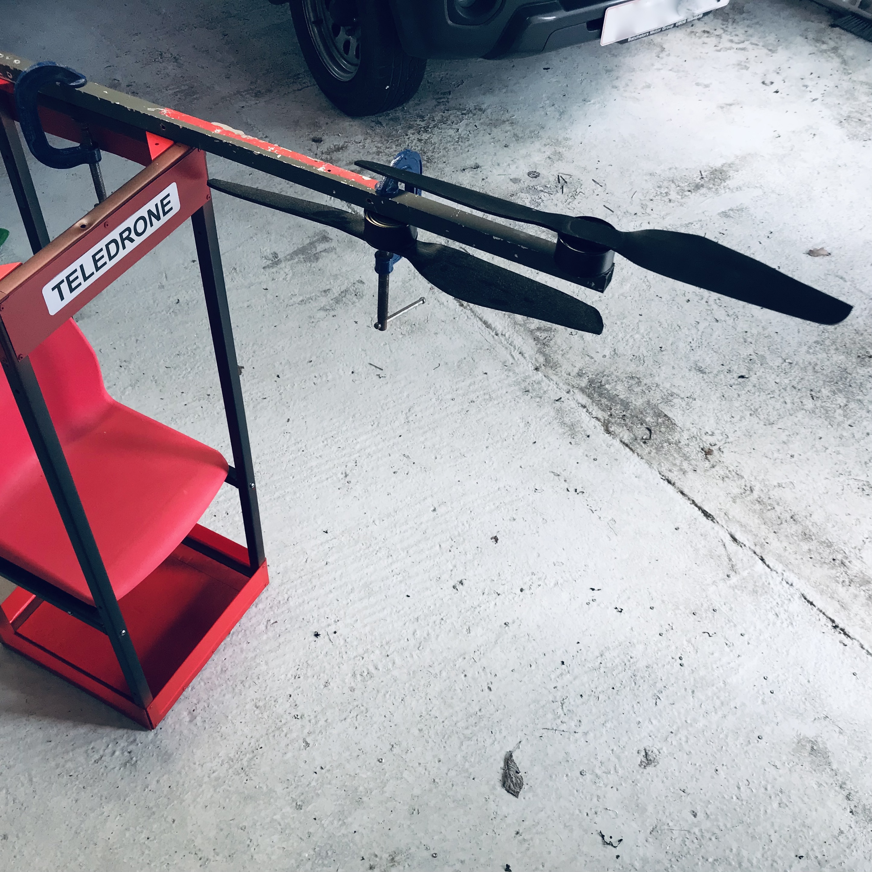
In the previous prototype which can be seen at https://evtol.news/teledrone-mk-vii these had to run way above spec in order to raise the 17.50 kilo gross weight of the aircraft, and so it will be interesting to see if the offset pairs of propellers are able to produce the extra thrust that we could expect... on paper at least.

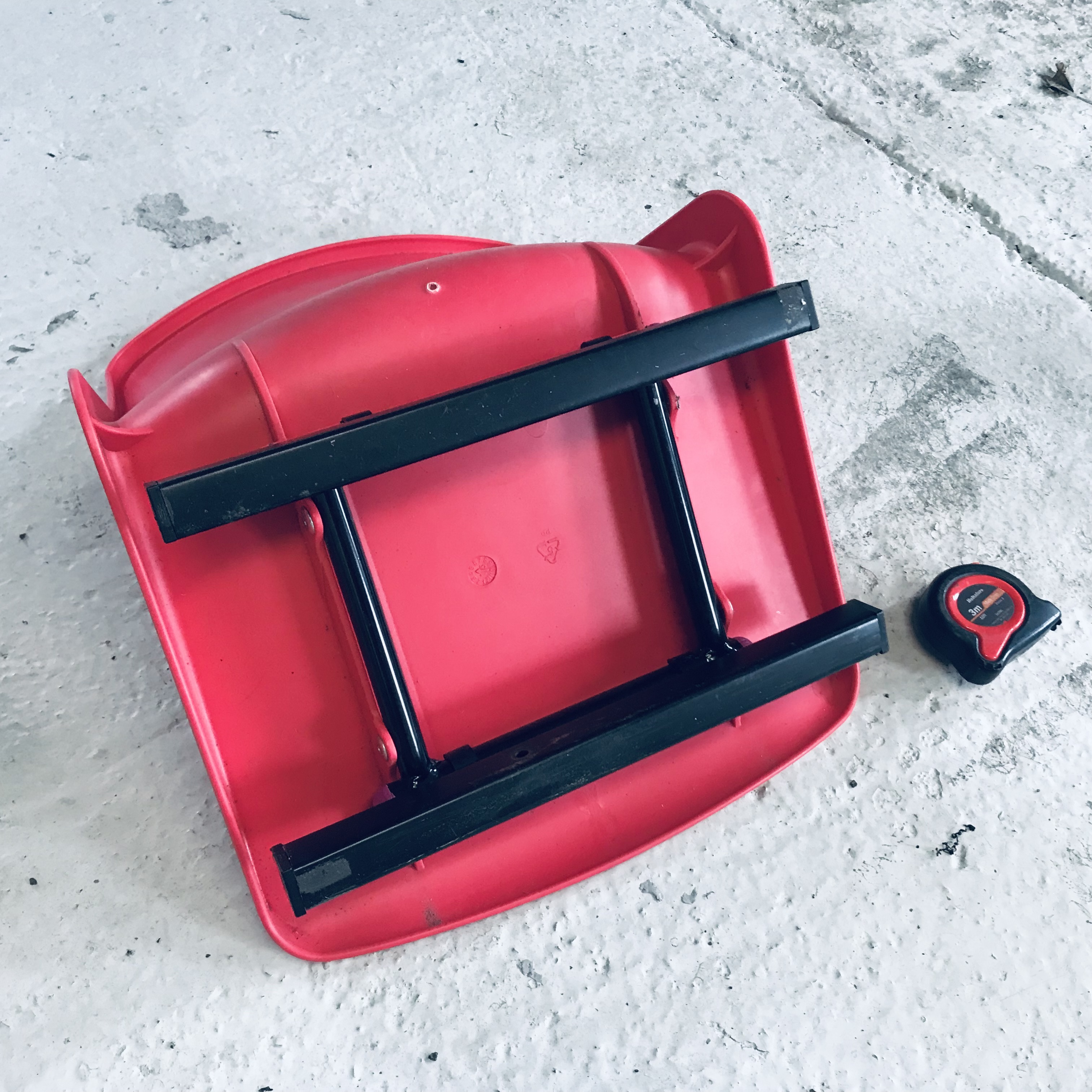
Key considerations in allocating these components are the fact that the centre of the drone has ideally to be preserved for the flight controller, whilst all else has to avoid each of those bolts that retain the accommodation booth below.

A benefit of re-using these parts, too, is the fact that they are already wired together.

Meanwhile a benefit of producing these personal air vehicles in kit form (which Jetson set out to do but changed their minds, doubtless in view of the relative complexity of the product) is that you don't would not have to worry about what goes where unduly.

Finally a benefit of the outline we are working on here is that it is relatively flexible as to which components to choose and as to what goes where. Conventionally humans have had to fit helicopters, whereas with PAVs we could be entering a world in which helicopters are tailored to the size and weight of different people... bizarre, but true.

Homebuilt Helo #31


Here's an overview, and I've removed the lower trim as I'm unconvinced it's necessary.

Reviewing progress, this airframe prior to fitting out weighs thirteen pounds or 5.90kg.

By the time you add batteries (6.20kg), motors (2.60kg) and ESCs (0.90kg) at thirty-five pounds (15.60kg) it is only fractionally lighter than the last prototype, which featured a quad overhead and another at ground level.

Nonetheless with the kit-build market in view I do believe this is the most practical of the many previous layouts that we've built and flight-tested.

Homebuilt Helo #30


Here's a view of the modules bolted together with wing-nuts, and it is a good idea to mark the 'front' of both the accommodation booth and the drone to allow for marginal misalignment of each. A benefit of eVTOLs is that rigging is not so critical as it can be on conventional aircraft because the flight controller will compensate for any offset.

Homebuilt Helo #29


Invert the box and overlay it upon the drone body before marking the drill-holes that will locate the bolts attaching the two modules together.

Saturday, March 30, 2024

Homebuilt Helo #28


Apply an undercoat if you've unless you've used water-proof material throughout and in order to render the drone in phone-box red later. A pole can be slipped into one of the airframe arms in order to flip it over like this for painting both sides.

Personal air vehicles are invariably black nowadays, which would have delighted Henry Ford. This however is because the material of choice for their construction has always been carbon fibre sheet.

Happily this too comes in red however nowadays.

Take a break now... you've done well!

Homebuilt Helo #27


... squeezing some insulation foam in and applying more silicone around the perimeter before fixing the upper cap in the same way as the lower.

Homebuilt Helo #26


With the ply fixed in place, flip the frame over and apply a bead of silicone around the edges before...

Homebuilt Helo #25


With the four spars bolted together, flip the frame over and rivet the ply starting with four around the sides before moving on to the corners. Care is required here to avoid the 6mm bolts that secure the spars here.

Homebuilt Helo #24


I've gone for 3.60mm plywood to cap the centre-section as (a) the sheet-metal shop is closed at weekends and (b) ply is three times cheaper.

This done, tee up your cantilevers as they'll appear on the prototype, so for example I've retained the best cut of ply for the topside, whilst this here will be the base.

As a result we've gone right foot forward as we'll be entering the air vehicle from the left side. This is standard practice in the air and at sea and stems from the days that boats were steered with a paddle down the right or 'steering board' side.

If you're left handed you may then prefer to reverse the arrangement and bear in mind you can do this at any time prior to fitting the flight-controller ~ and even afterward if you're prepared to operate with an inverted controller affixed the underside.

We need now to mark up a drill-hole to fix the ends of each spar to the adjacent one, and so there is an inch-and-a-half to come off the 15" perimeter length, besides 5mm for the width of the M6 threaded insert that caps the spar.

This provides for a 6mm drill-hole around 340mm from the end of each spar in order to secure.

Don't be afraid to sub wood here and there for prototyping. Germany's first fighter jets were constructed in wood, as was the Mosquito: both among WW2's fastest aircraft.

Friday, March 29, 2024

Homebuilt Helo #23


With the spars reclaimed from the last prototype, I see from the paintwork that this will be the third aircraft in which they've served. They're only 36" however, one inch shorter than the draft plan we're working from, and so it pays at this stage to stage a mockup with a couple of G-clamps, a pair of (dummy) propellers and two tins of tuna.

The tins of tuna subbed for motors in a PR shot prior to fitting out the prior prototype and all being well I shall be consuming their contents later in a bowl of pasta, with it being Good Friday today.

I like what I see, as the arrangement is more efficient than coaxial props while cutting the length of each cantilever effectively in half.

In theory any number of motors could be arranged along each arm this way, so don't bother trying to patent the idea now that I've let the cat out of the bag.

(After years pursuing IP I can say though that this would be considered obvious "to those practised in the art" as examiners like to say.)

N.B. the motors are going to be switched in reality, so that that propeller nearest you is going to be overslung and thus further from harm.

Tuesday, March 26, 2024

Homebuilt Helo #22


You can't afford to be sentimental when it comes to prototyping, and the 36" spars on this previous prototype we can re-use on the current.

For those who haven't followed the blog, we've built and/or flight-tested a number of variations to identify the best way of producing drones at the scale of people-carriers.

I liked the notion of quads separated like this, but for a flight-controller to handle all eight motors at the corners of a virtual cube called for a rigidity that in turn increased the weight, cost and complexity.

Which is what we're trying to eliminate with the subject of current effort.

It was Steve Jobs who said design was as much about what you took away, as much as what you might add.

Demolition is therefore set for the upcoming Easter weekend, in lieu of an egg-hunt.

Homebuilt Helo #21


I've revised the original draft to show our increase in the body from 14" square, to 15".

Discounting the propeller disks our proof-of-concept has a foot-print some 61" square, though as the triangle shows, turned at an angle it can be slid into a space 45" wide.

(The angle you can also calculate, though it's not something I do loading a roof-rack.)

The lengths of the cantilevers is then 23" + 15" - 1" = 37".

As spars retail in metres in Europe there's therefore an argument to leave them uncut at 1000mm, which is only some 2.50 inches longer... and what's that between friends?

All prototypes are prone to expand in both size and weight and this is one reason why.

Meanwhile, here's my go-to right-angle calculator:

Homebuilt Helo #20


And this is how it should look once it's all logo'd up.

I'm unconvinced it needs a base besides corner brackets and an open framework, and it may yet trend that way as we scale to full size.

For now it does leave room for hand luggage, which in this case is stored beneath your own seat rather than the one in front.

I've not bothered to match the uprights, as it involves too much paint if black and not white tubes are used (whilst this here was made with leftovers).

For past prototypes I built the drone first and adapted a box afterward, and it's right that we've started out here with the human frame and adapted an airframe to suit. 

We've a drone to build now and then ~ should it prove necessary ~ an undercarriage.

(The last prototype flying with the same power weighed 17.50 kilos, whilst this module adds just 4.20 kilos toward the next.)

Homebuilt Helo #19

When I was building Airfix kits as a kid there was nothing better than that point when the Humbrol enamel paint had been applied and all that remained was to apply those fiddly decals.

At that time airliners used classical colours and stripes along their window lines until PanAm came along with all-white Jumbo Jets and everyone followed suite.

At the time it looked spectacular ~ as anything new invariably does ~ at least until we realised that it actually looked shit.

You can use the image file above so long as you acknowledge the source, which is to be done by building a shrine to me with a life-size statue to which you pay obeisance.

Homebuilt Helo #18


Pop-rivet the brackets in place whilst the airframe is still inverted, and turn upright as here to admire your handiwork for a moment.

If you think this is not a secure means of fastening brackets, incidentally, try removing them if ever you've installed them upside down... as I have on occasion.

Our 'flying phone-box' is now ready for painting, which is the fun part or at least until you die from emphysema some years afterward.

If you're working in the cold (as we do all year in the UK) then bring in both the paint and the space-frame for a 'warm soak' prior to application, which generally requires a temperature of 15 degrees centigrade.

N.B. The only difference between Celsius and centigrade is the first is harder to spell.

Homebuilt Helo #17


With the ballasted space-frame in place, carry out a risk assessment.

I've done that, and it's primary finding is that if one of those bar-bell weights drops on your head during the next phase, then there probably won't be a next phase.

That done and wearing a hard-hat, hi-visibility tabard and goggles (yeah, right) set the four kitchen-cabinet corner brackets in place before marking those holes adjacent the space-frame with a pencil or bradawl.

These are going to be supporting your weight during flight, so make sure whilst you're at Home Depot that the assistant has selected aerospace-grade cabinet brackets.

Failure to do so invalidates the warranty that I won't be providing anyway.

Homebuilt Helo #16


Now you need to invert the airframe and set it on a level surface prior adding ballast to ensure that it's set as true to the vertical and horizontal as possible. Remember to allow for the phase of the moon during this procedure.

Homebuilt Helo #15


Drill out the M6 holes that will locate the lateral spars which support the seat itself.

Notice firstly that you can twist these side-bars in order to drill them out that much more easily, and also because they will need to be turned through ninety degrees from the time we marked them with the bradawl.

Secondly that the lateral supports will be fixed as all else with domed M6 bolts that are fastened happily using an IKEA Allen key.

(If you've not heard of IKEA, incidentally, then you shouldn't be building helicopters).

Homebuilt Helo #14


With the airframe inverted, align a spare threaded tube-insert with the one in the end of the lateral spar, and pierce the framework at that point with your trusty bradawl.

Repeat for all four points at which we need to drill out.

Homebuilt Helo #13


Now with the laterals in place we need to locate the chair. At full scale you can sit in it and slide it back and forth until you feel at one with the Universe, although at this reduced scale you'll be working by eye.

As it turned out anyhow the pair of lateral spars proved to be equidistant from front and rear of the space-frame, but this is as good a way as any to be sure.

I have now taped the seat in place, and you will shortly see why.

Homebuilt Helo #12


In the event, after using the bradawl (pointy thing for making pilot holes in wood) as a guide I simply fixed the conduit clips with self-tapping screws.

Yes, I hear what you're saying: "Maybe good enough for Boeing, but not for my aircraft".

And so yes, you can fix the clips to the laterals using countersunk M4 nuts and bolts, should you so wish.

Here then is a picture of the laterals in place once clipped to the chair.

Homebuilt Helo #11


We've determined that the conduit clips need to be spaced 130mm apart to secure the seat, and this means we can mark holes 10mm from either end of these laterals, which is a nice round number.

Homebuilt Helo #10


So as not to make the mistake of setting the seat-frame up and discovering it doesn't fit the space frame, the thing to do now is to fix the lateral seat supports to the seat prior to fixing them to the space-frame itself.

To do this we begin with a broad measure of how far apart the conduit clips are going to be, and I've settled here on 130mm between centres. The reason I work to centres is that we can then set the clips on the seat supports and mark the drill-holes with a centre-punch... something that like me you won't have used since metalworking class.

Homebuilt Helo #9


I've measured the seat height using a kitchen chair, although there are ergonomic text books out there that provide stock measures like these. It's around 18" and so at the 5/6th scale we're working at, that's around 15" above floor-level.

Here I've cut four lengths of tube of 13" apiece, although the M6 threaded inserts at either end amount to around a centimetre off that, which meant that I cut to 320mm.

Fore-and-aft sections are fixed in place at the predetermined height with dome-head bolts ideally, for aesthetic reasons, with the lateral seat supports eased into place for a look-and-feel.

Counting 50 more pop-rivets, four corner brackets to be used soon and a can of red paint we've spent an another £9.75, bringing our total spend to just under £20 to date.
 

Monday, March 25, 2024

Homebuilt Helo #8


For the shear webs at the lower end I've used leftover perspex, and the same off-cut I have used to cap the underside of the accommodation booth. Then in common with a past practise I've bolstered the inside of the base with 1" Celotex insulation board of a type more often used to insulate your home.

Around the inner edges of the top and bottom ends of the booth you can run a bead of silicone, which both helps fix the edging and dampens vibrations at the same time.

Homebuilt Helo #7


We'll be adding shear-webs top and bottom to the cage to stiffen things up, and I've used leftover alloy sheet for this which is 1.20mm gauge and about three inches wide.

In past prototypes the amount of material I've used has been way over spec for proofs of concept, and besides the inevitable switch to carbon-fibre spars will render a lot of it surplus to requirements anyway.

For technocrats amongst you, that's 4 x 12mm pop-rivets I'm using, tho' 10mm will do.

Sunday, March 24, 2024

Homebuilt Helo #6


A top-down view of the box, which I've rigged up to measure the seat still fits. It does, and in fact the depth of the box could be reduced by an inch to make it 15" by 14".

The seat back is reclined slightly, however, so beside the fact this it's nice and square there still remains wiggle room for fixing a back to the space-frame as per phone-box.

Were the box to be the full 45" high (allowing me a little head-room at full scale), then as it is 15" square then we can take as a rule-of-thumb that the box is three times as high as it is broad and deep... and I do like a good rule-of-thumb.

That's sufficient for the day though, and I need to mow the lawn.

Homebuilt Helo #5


For this exercise you will need a flat cap, set-square, chair and tape-measure.

It's best done with a friend, bearing in mind they may no longer be a friend afterward.

Set the chair against a wall and ~ here's the easy part ~ sit on it. Raise the set square to above head height so as to rest gently on the cap.

Using what's set to be the next hatha yoga move, mark a line on the wall with a pencil level with the base of the set-square.

This, you can tell people at parties, is your height whilst sitting down.

For me that's 52 inches, which at the scale we've chosen to use is around a 44" mark.

It means we can just ~ using artistic licence ~ use one metre uprights that are readily available (in Europe at least) at reduced cost, though we'll rummage in the workshop for the options here.

Don't forget that the tube-connectors add two inches to the height of the 'phone-box' so that we'd be talking nearer the 42" measure.

And frankly nobody would notice the difference on the day.

Homebuilt Helo #4


We could use CAD/CAM for this exercise, I've chosen to use the conservatory instead.

For we need a broad brush idea that the dimensions guesstimated prior to amputation of the chair legs are still good to go, and it appears that they are ~ basically a box that is 15" square.

The seat is actually wider than it is deep, although we shall forego the temptation ~ it being a Sunday ~ to base the airframe on an off-square foot-print.

I've done this in the past with stand-in booths, simply because people are generally a bit wider than they are deep unless they regularly supersize at McDonalds.

At the end of the day tho' it offends my sense of symmetry, and I'm not having it.

For this exercise you need scrap tubing, three-way tube-connectors and conservatory.

Homebuilt Helo #3


Here's what I mean.

I've re-used the plastic end-caps by way of a prosthetic, and the legs will go into the recycling bin in order to minimise the damage to the planet stemming from my effort.

For the weight-conscious amongst you we've just shed two of our five pounds, which makes this chair a contender for slimmer of the year.

We could replace what's left of the steel tubing with alloy or carbon-fiber... but that's not what we do, is it?

Homebuilt Helo #2


The bulk of the weight of the chair lies in the steel-work, most of which is surplus to our requirements. I'll use a method I've used before and retain enough to fasten it to the deck of the passenger compartment using conduit clips. I've left one off for you to zoom in on, whilst the others are clipped in place already.

We shall now amputate the legs of the chair with an angle-grinder, and doctors advise there is no need for anaesthetic at this stage of the operation.

Homebuilt Helo #1


Let's start with a chair.

This one cost me £5 on eBay and a return trip to Winsford (but I won't hold it against them).

It's a child's chair, in an effort to match a scaled version of our proof-of-concept. Back home however I note that it's around 15" square as against 18" for the adult seat that I have already, so we're talking a 5/6th scale.

That will be fairly convincing to look at, although it does render the motors and rotors rather smaller than they'd be in reality. Propellers for personal air vehicles range from around three foot in diameter to nearer five, and those we have already are just 22". 

That scales them up to only 27" and so somewhat short of the minimum required, yet the idea of a proof-of-concept is literally to prove to people that the design is a flyer.

Quad Squad

My gut feel is to run with this one.

We've a constrained budget, and so it's not worth trying to compete with the likes of Jetson or Pivotal who've years of development and substantial investment to boot. My instincts are to develop for the home-builder, and beta-test the most economical and efficient means possible of getting airborne in a straight line.

I've flipped the design horizontally, as we're going to develop for an underslung seat as well as a stand-up booth and we'll be starting out with the former. Reasons for doing so are the fact that (a) it's easier to make and (b) people are more comfortable with a seat when it comes to pleasure flights... of which I've operated many in my time.

Accordingly although it can be designed left-foot first instead of right-foot as here, I've found from exhibiting quads of this sort that it is best approached from the left ~ bearing in mind that approaching the vehicle you'll be taller than it, and one of many advantages to this design is that there's nothing to walk into whilst doing so.

Saturday, March 23, 2024

Drone Bone


Deployment in the field is likely to be key to the practicality of personal air vehicles and although I've always preferred two-dimensional constructions over stacked units of whichever kind, I'll make an exception for this arrangement, which as ever has been drawn from the back-catalogue.

The tic-tac-toe arrangement of octocopters has long been a go-to choice for projects around the world focussing on rough-and-ready construction of personal air vehicles.

It can be used to advantage here, however, by its division into identical 'bogies' bearing four motors each and with a layout like a dog-bone.

Once eVTOLs are scaled to include the human form, they need to be adapted to all of those other appurtenances of life that is equally so: including cars, ceilings and doors.

It is altogether too easy for home-builders to make boats or aeroplanes which require disassembly of either the craft or workshop on completion in order to extricate them, and vehicles of this kind are no exception.

And afterwards your talking roof-racks or trailers to reassemble or deploy them in use, and as such we need to start as we mean to continue.

We're likely to work to around two-thirds scale for a proof-of-concept, in which case the centre-body seen in the diagram is 14" square, the propellers remain 22" diameter and the airframe (discounting the swept area of the propellers) is 48".

Thus even at this stage it is clear that the assembly will only slide into the rear of your hatchback should the modules remain separated for transport.

For you learn nothing about eVTOLs until you've had to tote them here and there, and I've friends and colleagues who've had to trailer them over half the width of the USA.

Thursday, March 21, 2024

The Ugly Duckling


And this is what I mean... maybe doesn't look the part but it's eminently doable whilst safer than a quad and more efficient than an X-8.

An ugly duckling though which I'm sure would prove to be a beautiful swan in flight?

Wednesday, March 20, 2024

Draft Excluder

The second of a thousand steps, and what I use to exclude (or include) options at the outset is a rough outline that I draft in Apple's Pages app. I worked in computers when PageMaker was introduced, and was subsequently rendered obsolete ~ as were WANG Word Processors ~ by the improved functionality of programs like Pages and Word.

I have been known to sketch these outlines on the workshop floor (as indeed they did in chalk at the time the Titanic was built) but this is quicker, less messy and equally enjoyable.

Here we can see straight away that the eight-ball layout is not as attractive as might first appear, bearing in mind that each pair of propellers rotates the same way. There is no problem with this if the cantilevers are extended to 18" around the 14" centre-section.

Left as close as they can be to the centre-section as in the lower half of the diagram, however, then diagonally adjacent propellers rotate efflux in the same direction; which is decidedly inefficient. Note incidentally that from the top each pair of propellers has to rotate clock-, anti- clock- and anti-clockwise in conventional quadcopter practise.

Benefits of the layout are a compact foot-print along with a concentrated entrainment of downdraught that adds to efficiency in the hover... whilst disadvantages include the fact the spars do not lie in the same plane unless separate cantilevers are attached to four-way connectors at each corner of the central square: which at any scale adds the the cost of specialised product that might otherwise not be necessary.

The choice as often as not in designing eVTOLs lies in that between 'geeks' and 'jocks'. One of these might not look the part but passes aerodynamics with distinction, whilst the other goofs the exams but eminently looks the part.

What we choose going forward is thus divided between two goals viz. do we want the most economical means possible to get airborne, albeit at an acceptable level of risk given a single component failure? Or do we want to design a commercial product a la Blackfly's Opener or Jetson's One from the get-go...

...that comes neither cheap nor quickly?

Sunday, March 17, 2024

The Sermon on the Motor Mounts


Why do we do this?

Well I've lived a long time and seen computers develop from kit-builds that frequently failed and needed tending by high priests of the "computer room" of whose fraternity (and it was almost invariably male in those days) I was briefly and ineptly a member.

But now we barely give the equipment a second thought, devoting ourselves instead to what it can do.

In the realm of aviation, single-seat aircraft have always led a troubled existence and in the way that advancing nations like China evolve from bicycles toward electrical EVs weighing two or more tons in an effort to move individuals from A to B, so advantages of eVTOL will evolve toward where the money is most likely to follow: which is it, but with wings.

Nonetheless the most numerically successful motorised form of transport of all time has been the modest Honda Cub, which was specifically designed for noodle delivery in the narrow back-streets of Tokyo and conquered the world from there. The earliest form of transport common to all civilisations too was likely to have been the litter or sedan chair, which was basically a box-seat with a human porter at either end prior (a) roads and (b) wheels.

Most of the best work I've done on advancing the art of eVTOL has been lying awake at three in the morning, at which time the outline see here was sketched out. French exercise books incidentally are squared and ours in the UK are lined, which is likely the reason they build Airbuses there and not here.

For really it's a time to return to our roots, and build something we set out to do in the first place, which was exactly that: a flying box-seat with an octocopter on top.

It has really to be an octocopter for resilience, but from the outset this was one with a difference because uniquely it was a pair of quads stacked one atop the other with overlapping propellers which co- instead of contra-rotate: a type of 'virtual quad' safer and more efficient that plain-vanilla four-motored multicopters.

You can read about it more here: https://www.tdcommons.org/dpubs_series/6778/ but don't take my word for it and let physics do the talking instead.

Fact is though, some four years down the line and with all of the experience that we gained building and flight-testing a half-dozen different configurations at half- or full-scale... it would be altogether easier this time around.

The picture below shows the rig that was first fitted and successfully flown with an underslung box-seat that would accommodate an adult, albeit uninhabited. The only reason in retrospect that it was ever reduced to a quad was because of the logistical challenges connected with checking it for flights between London and San Fransisco in order to attend ~ and we were the only UK team that did ~ the competition there.

Like computers, this stuff will one day be taken for granted for all inventions ~ as the philosopher Schopenhauer observed ~ are eventually viewed as self-evident by us all.

Saturday, March 9, 2024

Further Notice


Picking up where we left off, what have we learned over the past six-something years?

Let's take the long view, as ever. In the week's news, songwriters' fears over their roles being substituted by AI. In Huxley's eponymous Brave New World, posited over ninety-five years ago, the songs were composed by computer... takes longer than you'd think.

We've successfully flown now with both four and eight props in the overhead and with four beneath the feet. We've also flown most recently with four in the overhead along with four around the feet. What the latter proved however was that the frame needed to be decidedly rigid in order for the flight-control computer to address the motors at each corner of a virtual cube.

That meant more both more weight, more expense and (quite literally) less flexibility.

Meantimes the eVTOL world has evolved into multi-seat multicopters at the scale of 'flying taxis' and a plethora of personal air vehicles of all shapes and sizes, although generally featuring reclining accommodation as per either the Blackfly or Jetson types that are (perhaps not coincidentally) nearest production.

Accordingly if an upright vehicle is to quite literally stand out from the crowd, then it has to be the most compact on the street and so far as TELEDRONE is concerned, not least because of the budget, that means we need to lose the phone-box.

As a consequence let's turn to a notion which arose in the workshop mid-pandemic, and which I've released publicly at https://www.tdcommons.org/dpubs_series/6751 and whose principal benefit as that it is field-deployable in portable parts. We've looked at any number of propeller layouts along the way ~ each having pros and cons ~ but for our 2024 build I'll use the most compact I've yet devised.

Again it is able to support either four or eight motors but either way it was revealed to  an adoring public just last year in the shape of UK registered design #6256068.

I hope you like it.